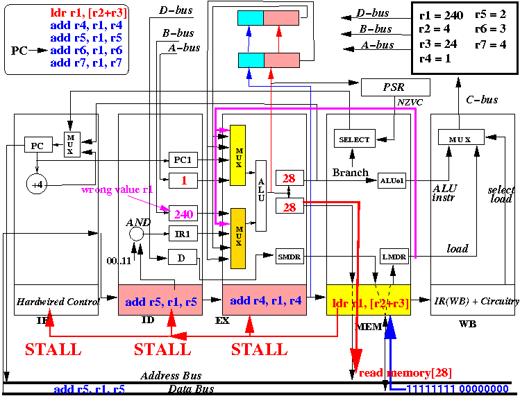
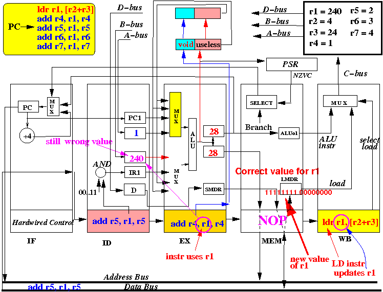
- Consider the
execution of the
LOAD instruction at the
moment that
it reads the memory:
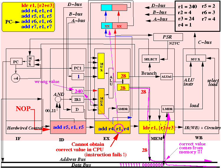
Notice that:
- The new value of
register r1 is
on the databus
The new value is not yet available inside the CPU !!!
- But the
next instruction
(add r4,r1,r4)
inside the EX stage
needs the new r1 value
right now to
perform
the operation
r1+r4 !!!
- It is impossible for
the CPU to
obtain the
new r1 value
of the EX stage
because:
--- The new r1 value is not available inside the CPU !!!
- It is impossible for
the CPU to
obtain the
new r1 value
of the EX stage
because:
Conclussion:
- If the instruction
"add r4,r1,r4"
to permit to complete execution
then:
- The instruction "add r4,r1,r4" will guaranteed to be in error !!!
We need to solve this problem first !!!
- The new value of
register r1 is
on the databus
- Solution
- When it is
impossible to
obtain the
data in time for
an instruction, the
only solution is:
- Stall (= slow down) the pipelined execution !!!
- When it is
impossible to
obtain the
data in time for
an instruction, the
only solution is:
- What does it
mean to
stall (= slow down) the
pipeline:
- When a CPU stage is
stalled, then:
- The stalled CPU stage will do nothing
That means:
- All the data inside the CPU stage are not changed
Important:
- The data in the CPU stage include the current instruction stored inside the CPU stage
- When a CPU stage is
stalled, then:
- How to
slow down the
pipeline:
-
Stall
some stages
of the
pipeline is done by:
- Stopping the
clock signal
(using an AND gate)
from reaching the
Dffs (= memory elements) inside
the CPU stage
(Then all memory elements in the stalled CPU stage will keep teir current value and will "do nothing")
Example: stalling the IF, ID and EX stages
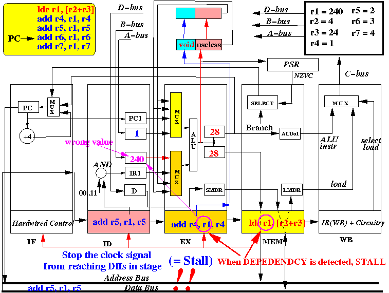
- Stopping the
clock signal
(using an AND gate)
from reaching the
Dffs (= memory elements) inside
the CPU stage
-
Stall
some stages
of the
pipeline is done by:
- When to
stall some
CPU stages:
- For performance reasons, we stall (= slow down) only when not stalling will cause an error
We have just discovered a stall condition (when we studied the LDR instruction):
- The
instruction in the
MEM stage is a
LOAD instruction
and
- The instruction
in the EX stage
uses the the
destination
register of the
LDR instruction as a
source operand.
- When this happens,
the instruction
in the EX stage
will use a wrong value
(This is a "read-after-write" data hazard - we read the register immediately after writing to the register)
- When this happens,
the instruction
in the EX stage
will use a wrong value
- The logic
for this
"Read-after-write"
stall condition
is as follows:
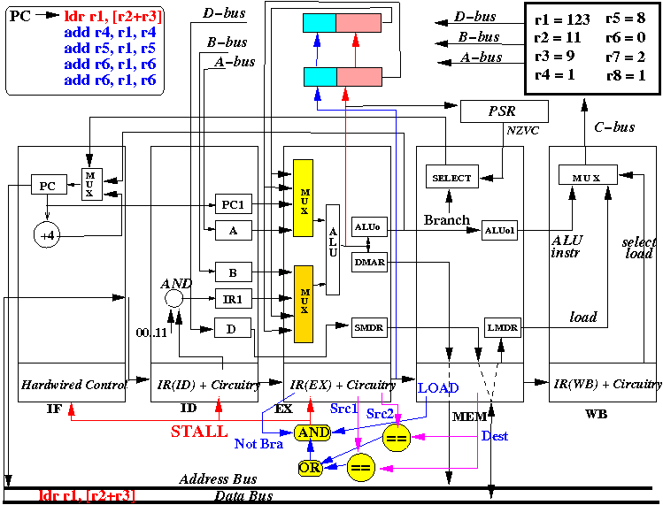
   if ( MEM stage contains a  LDR  instruction        &&
        EX  stage contains an ALU/LDR/STR instruction  &&
        (    Destination register of MEM stage == src1 reg of EX stage
          || Destination register of MEM stage == src2 reg of EX stage )   )
   {
      STALL: EX stage, ID stage and IF stage
   }
The circuitry used to detect the Read-after-Write stall condition is:
Note:
- If the EX stage is
stalled, then:
- The ID stage and the IF stage must also be stalled !!!
Example: if you are in a queue and someone right in front of you stops, then you must also stop !!!
- If the EX stage is
stalled, then:
- Let's consider
what
the solution that we
have designed will achieve:
- Right before the
"ld [r2+r3], r1"
instruction
fetches
the data from
memory:

- After 1 more CPU cycle:
- EX, ID, IF stages are stalled (= do nothing)
- MEM stage (and EX stage) continues operation
Resulting new CPU state:
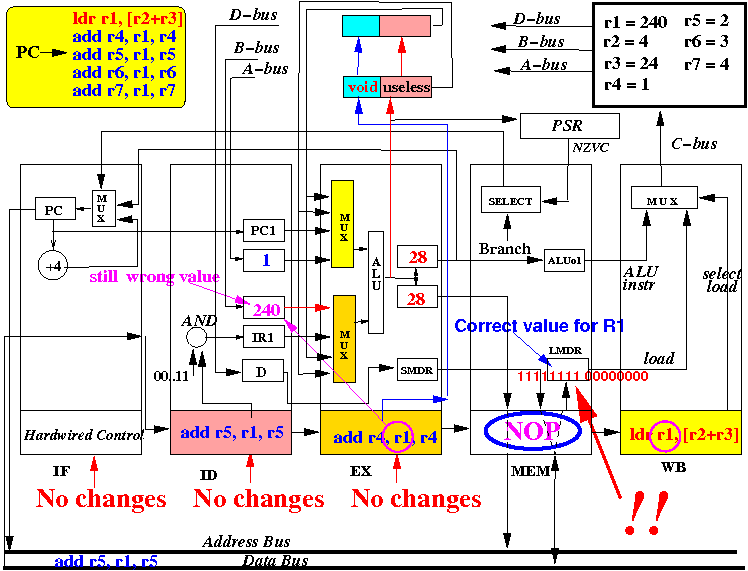
notice that:
- The ID stage
still has
a wrong value for
register r1
- But:
- The correct value for the updated register r1 is now inside the LDMR register inside the CPU !!!
Therefore:
- We can provide the correct value to the EX stage by using data forwarding !!!
- Right before the
"ld [r2+r3], r1"
instruction
fetches
the data from
memory:
- Notice the
location of the
information
needed to
check for
data forwarding:
- How to
forward the
data from
the LDR instruction to
the instruction in the EX stage:
- We must add the following
forwarding pathway connection from
the LMDR register outputs to
the input of
the MUXes in the
EX stage:
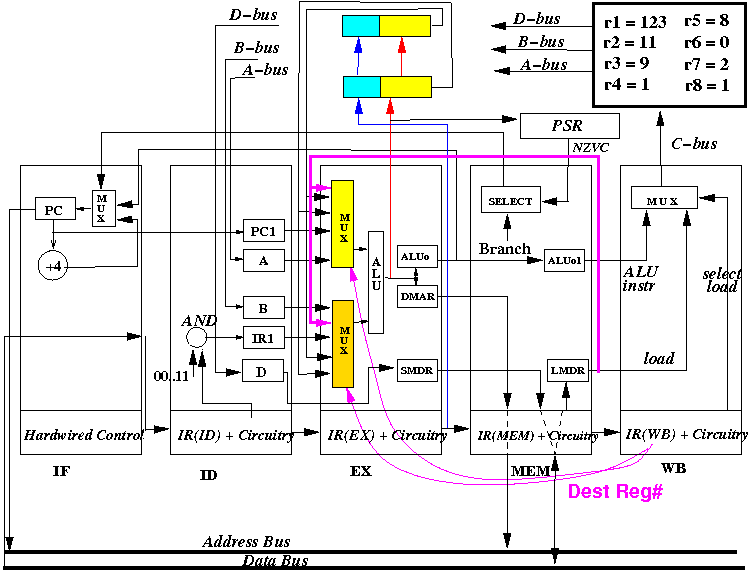
(Now the data in the LMDR can be used by the EX stage as an operand !!!)
- The MUX selection logic
must be updated to
include the
LDR instruction forwarding case:
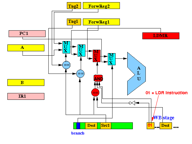
The selection logic for MUX 1 (= the top MUX in the EX stage) is:
   if ( Instruction == Branch )
      select PC1 as operand
   else if ( IR(WB) contains a LDR instruction &&
	     Dest Reg in IR(WB) == Src1 in IR)EX)  )
      select LMDR as operand
   else if ( tag1 == Src1 )
      select ForwReg1 as operand
   else if ( tag2 == Src1 )
      select ForwReg2 as operand
   else
      select A as operand
Implementing MUX 1 as a digital circuit is as follows:
The selection logic for MUX 2 (= the bottom MUX in the EX stage) is:
   if ( Instruction == Branch )
      select PC1 as operand
   else if ( IR(WB) contains a LDR instruction &&
	     Dest Reg in IR(WB) == Src2 in IR(EX)  )
      select LMDR as operand
   else if ( tag1 == Src1 )
      select ForwReg1 as operand
   else if ( tag2 == Src1 )
      select ForwReg2 as operand
   else
      select A as operand
No circuit for MUX 2 - you should be able to figure it out yourself.
- We must add the following
forwarding pathway connection from
the LMDR register outputs to
the input of
the MUXes in the
EX stage:
- To solve the
"Read-after-write" data hazard caused by
a load instruction, we must:
- Add some
forwarding hardware to
forward the content of
the LMDR back to the
EX stage
- Add circuirty to
detect if the
next instruction will
use the
fetched data
- If so, we must stall the instruction in the EX stage !!!
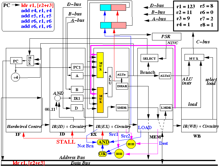
Now let us see how the improved pipelined CPU correctly handle the read after write data hazard caused by the LOAD instruction
- Add some
forwarding hardware to
forward the content of
the LMDR back to the
EX stage
Slideshow:
- Reconsider the following program that is executed by the IMPROVED
pipeline:
   ldr r1, [r2+r3]           R1=240, R2=4, R3=24, R4=1, R5=2, R6=3, R7=4
   add r4, r1, r4            Memory[28] = 11111111 00000000
   add r5, r1, r5
   add r6, r1, r6
   add r7, r1, r7
   ...
- Recall that the
correct behavior
is:
                       // Originally: R1 = 00001111 00000000
    ldr r1, [r2+r3]    // Instr will update R1 := memory[R2+R3]
                       //               or  R1 := 11110000 00000000

  Then subsequent instructions will use R1=11110000 00000000:

    add r4, r1, r4      // R4 = 11110000 00000001
    add r5, r1, r5      // R5 = 11110000 00000010
    add r6, r1, r6      // R6 = 11110000 00000011
    add r7, r1, r7      // R7 = 11110000 00000100
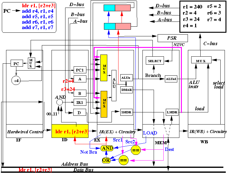
- At start of the CPU cycle, the IF stage sends out PC
- At end of the CPU cycle, the IR(ID) register is updated with the instruction fetched (ldr r1, [r2+r3])
State at the end of CPY cycle 1:
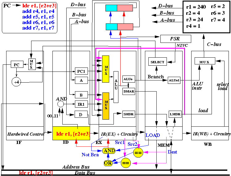
- The picture above depicts the content of the CPU at end of the first CPU cycle (and the start of the 2nd cycle) - same as before, the interesting stuff happens much later....
- At start of the CPU cycle, the ID stage sends out selection
signal that selects values from R2 and R3
- At end of the CPU cycle, the "A" register is updated with R2 = 4, the "B" register is updated with R3= 24.
- Also, at the end of the CPU cycle, the instruction ldr r1, [r2+r3] is moved into IR(EX) and instruction add r4, r1, r4 is fetched into IR(ID)
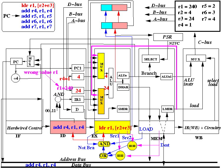
State at the end of CPU cycle 2:
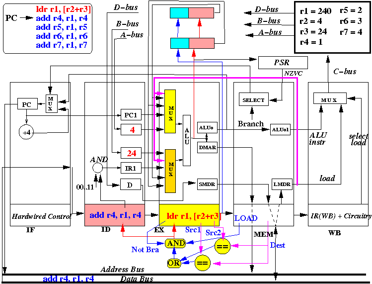
- The picture above depicts the content of the CPU at end of the second CPU cycle (and the start of the 3rd cycle) - still the same as before as the interesting thing will happen later....
- At start of the CPU cycle, the EX stage selects
values from R2 and R3 for the ALU, use the ALU opcode
to make ALU add the input values forming the result
4+24=28
(which is the memory address of
the "ldr r1, [r2+r3]" instruction)
Also, at start of the CPU cycle, the ID stage selects R4 (=1) and R1 (= 240, an old value !!) to be fetched into the "A" and "B" registers.
- At end of the CPU cycle, ALUo and DMAR registers is updated with
the value R2+R3 = 28 (= address value of the
LDR instruction)
Also, at the end of the CPU cycle, the instruction (ldr r1, [r2+r3]) is moved into IR(MEM), "add r4, r1, r4" is moved into IR(EX) and instruction "add r5, r1, r5" is fetched into IR(ID)
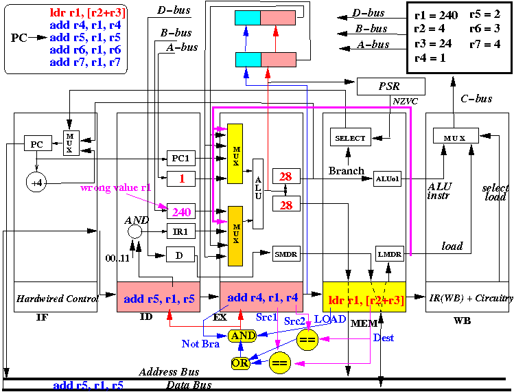
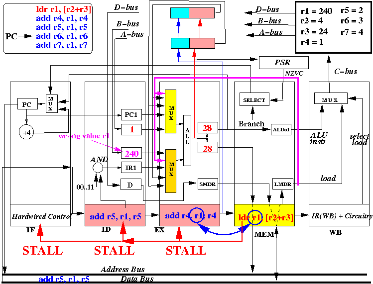
- The picture above depicts the content of the CPU at end of the 3rd
CPU cycle (and the start of the 4th cycle)
So far, the execution is the same as we have seen (when we execute a LDR instruction).
The change will will happen right now.... because the LOAD instruction in the MEM stage and it is being executed !!!
- At start of the CPU cycle, the
address in LMAR (= 28)
is sent
on the address bus
and the value in the memory location 28 is
being fetched. This value will arrive
towards the end of the CPU cycle (because the memory
is pretty slow).
- The STALL detection hardware
now
detects that:
- The instruction in MEM stage is a LOAD instruction
- The instruction in the EX stage will use the destination register (= R1) of the LOAD instruction right away !!!
The STALL detection hardware will issue a STALL signal to the EX and ID stages !!!
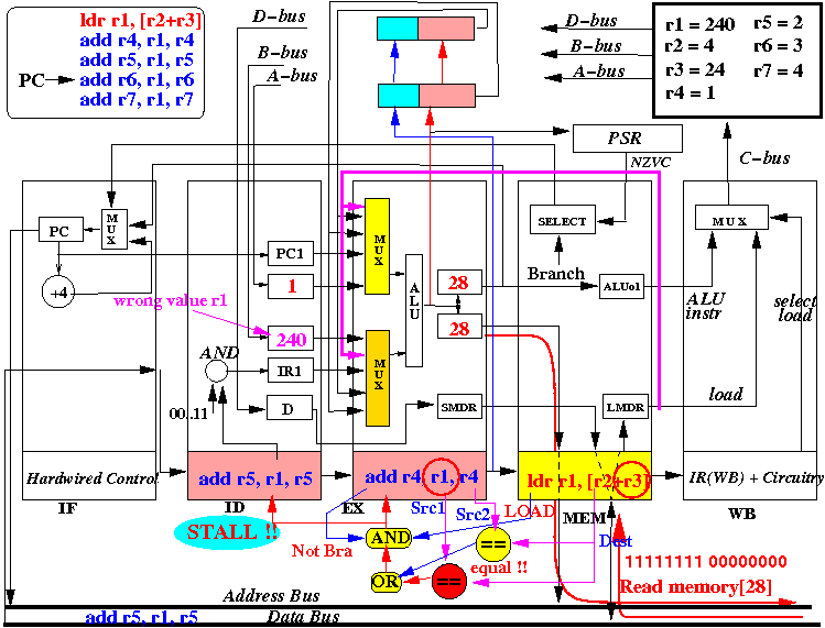
The ID stage and the EX stage are stopped (= will do nothing)
- At end of the CPU cycle, LMDR register in MEM stage is updated with
the value fetched from memory (4000).
Also, at the end of the CPU cycle, the instruction (ldr r1, [r2+r3]) is moved into IR(WB), but the add r4, r1, r4 instruction will remain in IR(EX), and the add r5, r1, r5 instruction will remain in IR(ID)
State at the end of CPU cycle 4:
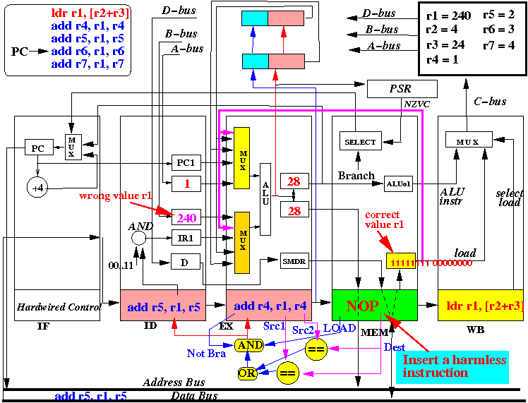
- The picture above depicts the content of the CPU at end of the 4th
CPU cycle (and the start of the 5th cycle)
- Notice that a NOP (harmless) instruction must be inserted into IR(MEM) to ensure that no valueable information is inadvertently altered by the CPU stages. A similar technique as that one used in the IF stage is used (see click here )
- The picture above depicts the content of the CPU at end of the 4th
CPU cycle (and the start of the 5th cycle)
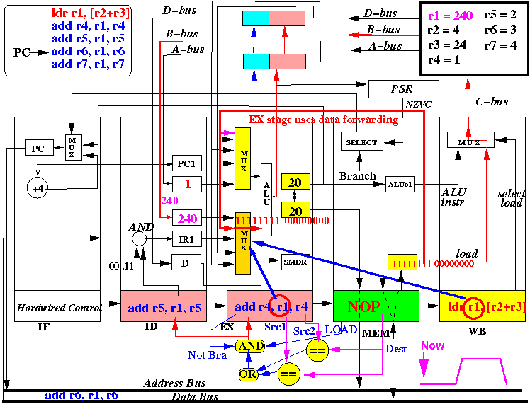
- At start of the CPU cycle, the LOAD instruction is in the WB stage
and because the destination register is equal to the
Src2 register in the EX stage,
the new (additional) forwarding hardware
( click here )
will detect
the dependent and
forward
the value in LMDR
to the CPU as second operand.
So the correct value of R1 will be used by the first ADD instruction add r4, r1, r4
- At the start
of the CPU cycle, the old value of register R1
is being fetched
but:
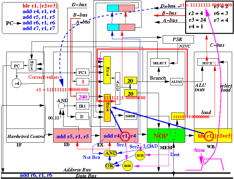
- This old register r1 value will be replaced by the new register r1 value after the middle of the CPU cycle !!!
That is due the way the general purpose registers are updated:
- The general purpose registers are
updated
at the rising-edge
(= at the middle of
the CPU cycle
- The registers in the ID stage are updated atthe falling-edge (= at the end of the CPU cycle)
If you want to know the details of this update technique, you can re-read the timing of the register updates here: click here
So the correct value of r1 will be fetched (and used) by the add r5, r1, r5 instruction.
State at the start of the CPU cycle:
State at the middle of the CPU cycle:
- At the end of the cycle, ALUo will be updated with
11111111 00000000 + 1 =
11111111 00000001,
which is the
correct value
because r1 = 11111111 00000000.
- Also at the end of the cycle, the "B" register will contain
11111111 00000000
(= the new value of
r1).
- And at the end of the cycle, the result of the ALU
(= 11111111 00000001)
is also stored
into
Forwarding Register FR1
along with the register tag "r4"
-
this Forwarding Register value will aid in "correcting" a subsequent
instruction that use R4 as a source operand.
State at the end of CPU cycle 5:
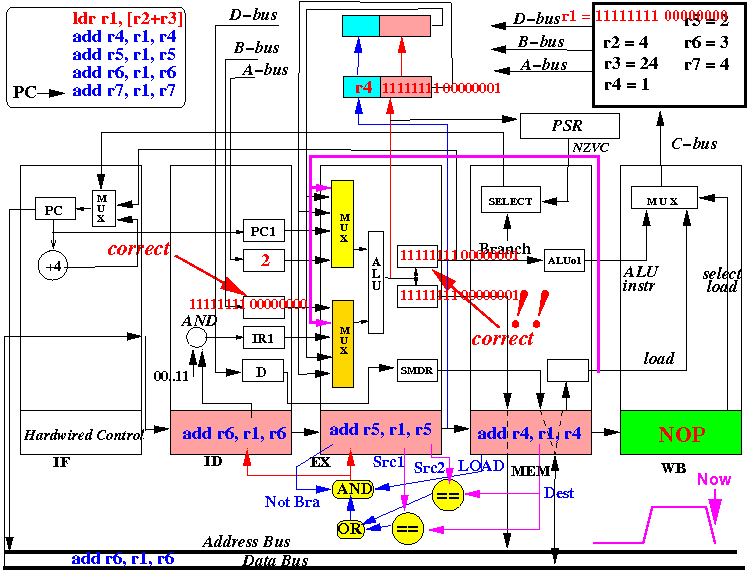
- The picture above depicts the content of the CPU at end of the 5th
CPU cycle (and the start of the 6th cycle)
- Clearly, all (ADD) instructions following the LOAD instruction will use the correct r1 value and will be executed correctly !!!
