Addressing the simplification made
in the
interrupt processing discussion
|
Computer with multiple devices that
can send interrupt requests
In an actual computer, there are more than 1 devices that can send interrupt requests:
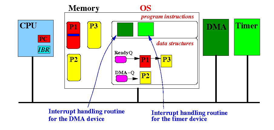
Each device will have its own interrupt service routine inside the Operating System
Real life computer with interrupt service
When the DMA device sends an interrupt request:
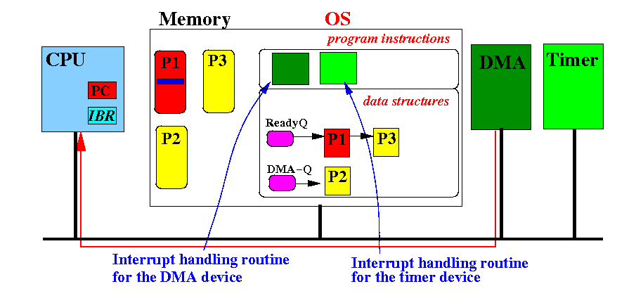
Computer with multiple devices that
can send interrupt requests
The computer system must run the DMA's interrupt service routine:
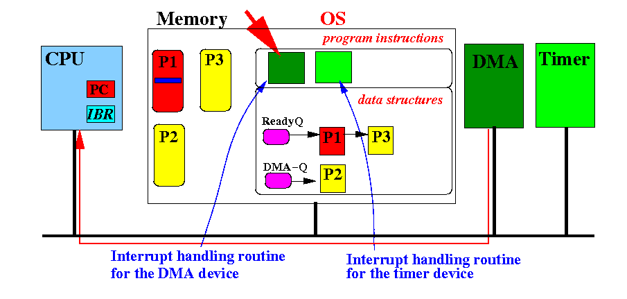
Real life computer with interrupt service
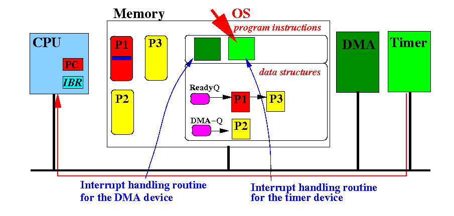
When the Timer device sends an interrupt request:

Computer with multiple devices that
can send interrupt requests
The computer system must run the Timer's interrupt service routine:
And so on (if there are more devices that can send interrupt requests)
The Vector Interrupt technique
|
Hardware setup to support
the vector interrupt
device identification and handling technique
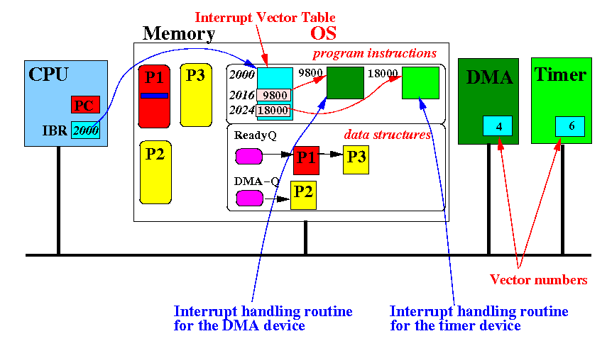
Each device is assigned a unqiue ID (= integer) called the vector number:
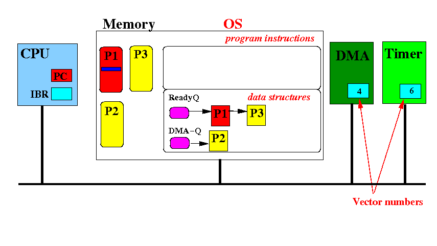
Example: the DMA device has vector number=4 and the Timer device has vector number=6
Hardware setup to support
the vector interrupt
device identification and handling technique
Each device also has its own interrupt service routine inside the Operating System:
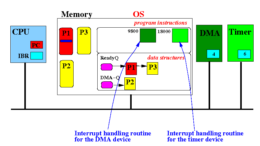
Example: the DMA's int serv routine is at address 9800 and the Timer's routine is at address 18000
Hardware setup to support
the vector interrupt
device identification and handling technique
The Interrupt Base Register contains the base address of the interrupt vector table:
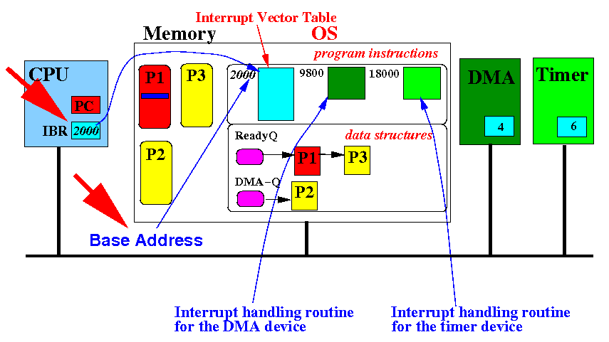
The interrupt vector table contains addresses of interrupt service routines (each address is 4 bytes long)
Hardware setup to support
the vector interrupt
device identification and handling technique
The address of the interrupt service routine of the DMA (vector number 4) is stored in entry 4:
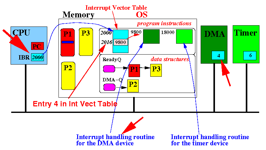
Entry 4 has offset = 4 × 4 = 16 bytes in the Interrupt Vector Table
Hardware setup to support
the vector interrupt
device identification and handling technique
The address of the interrupt service routine of the Timer (vector number 6) is store in entry 6:
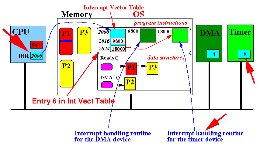
Entry 6 has offset = 6 × 4 = 24 bytes in the Interrupt Vector Table
Hardware setup to support
the vector interrupt
device identification and handling technique
Summary: the Vector number is an index in the Interrupt Vector Table
We will now discuss the vector interrupt technique that allow the CPU to run the correct interrupt service routine for the device that is sending the interrupt signal
The vector interrupt technique
used in today's computer systems
Suppose that the DMA device is sending the interrupt signal:
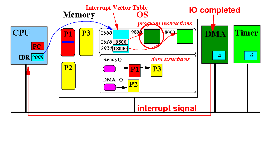
From the previous discussion, the Operating System must run the interrupt service routine at address 9800
The vector interrupt technique
used in today's computer systems
The CPU responds to the Interrupt signal by sending out the interrupt acknowledge signal:
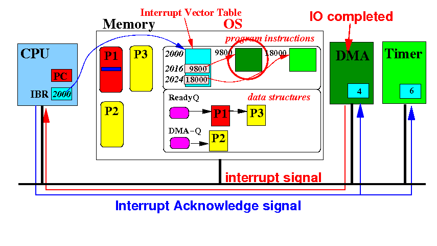
The interrupt acknowledge signal is received by all devices !!! (We now use the simplification)
The vector interrupt technique
used in today's computer systems
The Int Ack signal causes the (only) one interrupting device to send its interrupt vector on data bus:
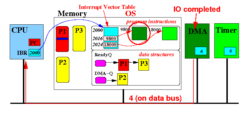
The CPU will read the vector number from the data bus and use it as an index (like an array index) !!!
The vector interrupt technique
used in today's computer systems
The CPU computes IBR + 4×VectorNumber = 2000 + 4×4 and reads the memory address 2016:
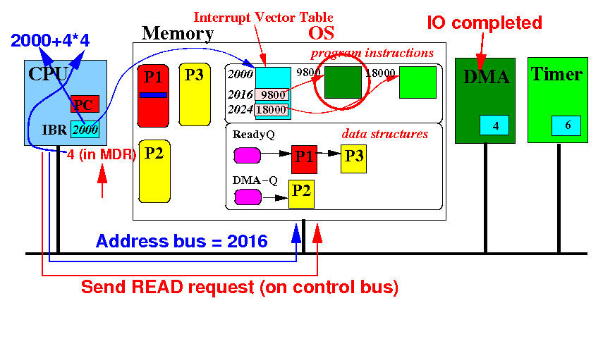
In response, the memory returns the value 8900 (in memory address 2016) on the data bus.
The vector interrupt technique
used in today's computer systems
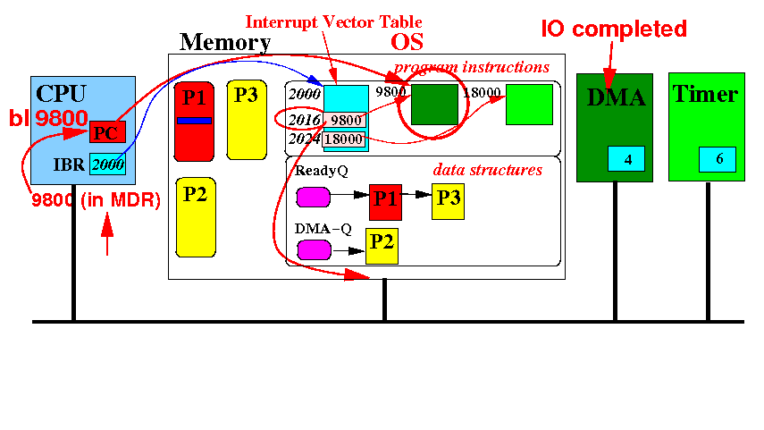
The memory data (= 9800) is read by the CPU and....
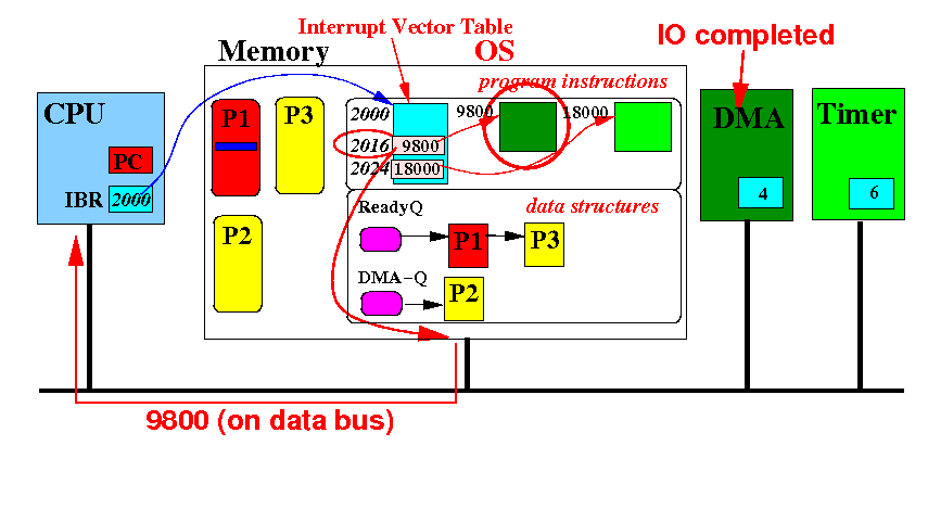
The CPU will call the subroutine at this address 9800 !!!
The vector interrupt technique
used in today's computer systems
Result: the CPU runs the interrupt service routine of the DMA device
We have already discussed this interrupt service routine in click here
Summary: IO communication
|