Review: what have we achieved ?
A computer program that executes an IO (e.g.: input) operation cannot continue:
  // Computer program (e.g.: Java)

  i = in.nextInt( ); // Performs an input operation

  i = i + 1; // Must use correct input value !!!
|
A (running) computer program that executes an IO (e.g., input) operation is paused until the input data is ready
Review: what have we achieved ?
Situation before the running (current) program performs an IO operation:
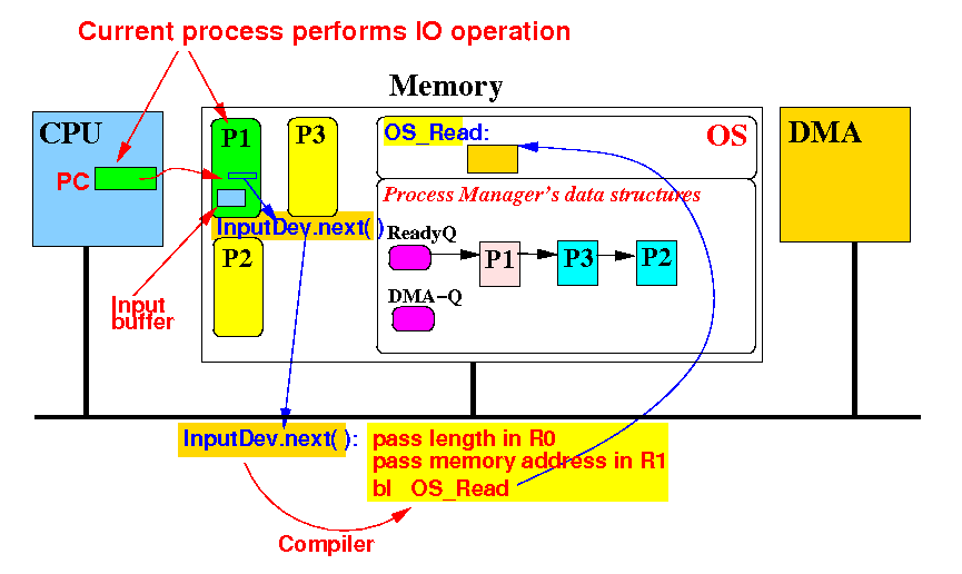
The current process P1 performs an IO operation
Review: what have we achieved ?
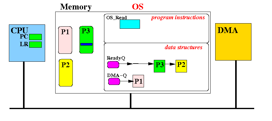
Situation after the running (current) program started an IO operation:
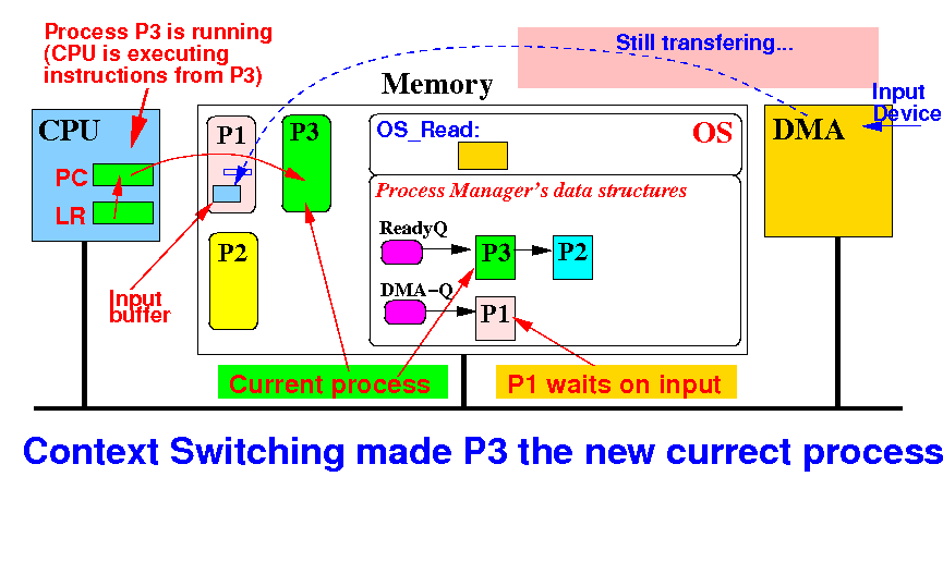
The current (running) process is now P3 and P1 is paused (waiting for the IO operation to end)
Problem: what happens when the
IO operation finishes ???
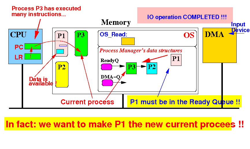
Situation when the DMA has finished the IO operation:
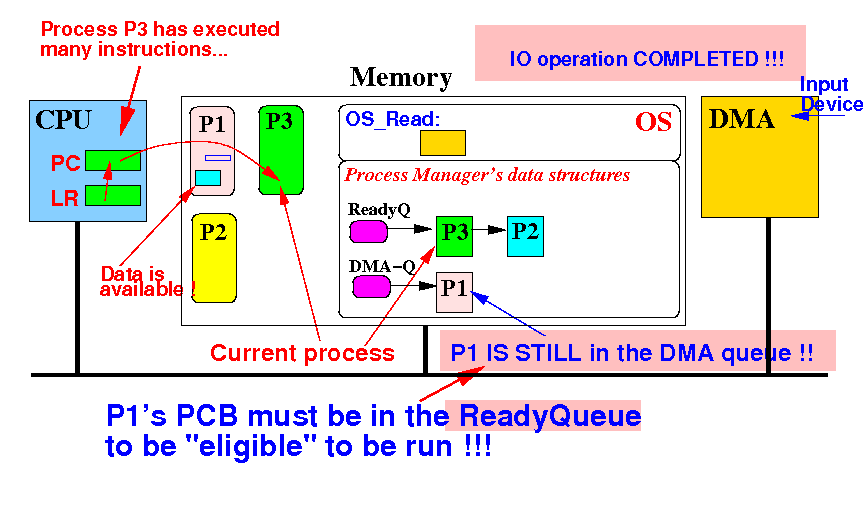
Problem: P1 will not run !! How can we make process P1 run again ???
Problem: what happens when the
IO operation finishes ???
Key: we must move P1's PCB to the Ready Queue (because these processes are run by OS)
Problem: the CPU is executing instructions from P3 -- what if P3 never stops ?
Background information needed to
solve the "IO completion problem"
The CPU has (at least) one interrupt (input) signal:
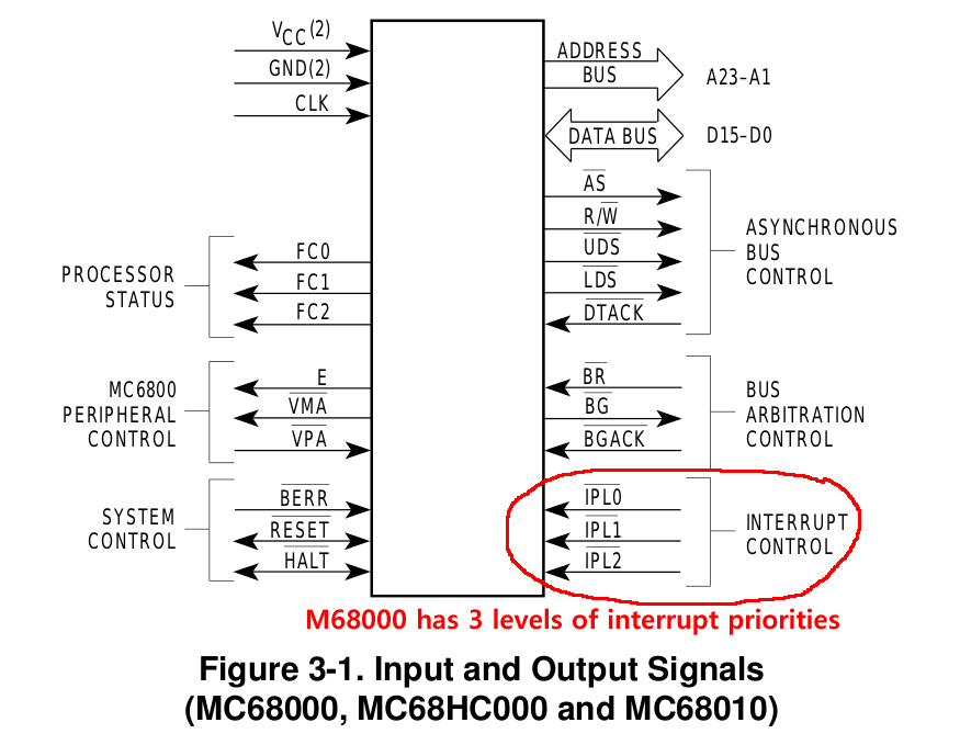
I will also need to amend your knowledge on the Instruction Execution Cycle...
Background information needed to
solve the "IO completion problem"
The complete instruction execution cycle actually has 5 steps:
|
The 5th and last step in the instruction execution cycle allow IO devices to interrupt the execution of the current process (program) (by the CPU !!!)
Experiencing interrupts and
interrupt processing
Compile and run the program /home/cs355001/demo/interrupt/interrupt.c
 while (1)
 {
   for (i = 0; i < 999999; i++); // Slows the program down

   putchar('.');  // Print "."
   fflush(stdout); // Make sure the character is displayed
 }
|
Output: (I typed some control-Z characters in the keyboard)
cs355@aruba (1500)> ./interrupt Setting up interrupt signal for SIGTSTP (control-Z) ............^ZYou typed control-Z........ ......................................... ...............^ZYou typed control-Z..... |
Experiencing interrupts and
interrupt processing
How did I make the infinite loop take a detour: (a little bit of CS350 Systems Programming):
void Int_Handler(int dummy)
{
   printf("You typed control-Z");
}

int main()
{
 sigset(SIGTSTP, Int_Handler); // Setup Interrupt Handler

 while (1)
 {
   for (i = 0; i < 999999; i++); // Slows the program down

   putchar('.');  // Print "."
   fflush(stdout); // Make sure the character is displayed
 }
}
|
Typing control-Z in the keyboard will send the SIGTSTP interrupt signal and causes the CPU to make an "unprogrammed" subroutine call !!!
A 2-steps discussion
on interrupt handling
|
Background: the
Interrupt Base Register
The CPU as discussed cannot service interrupt requests:
The CPU needs an additional special purpose register !!
Background: the
Interrupt Base Register
The CPU has a Interrupt Base Register:
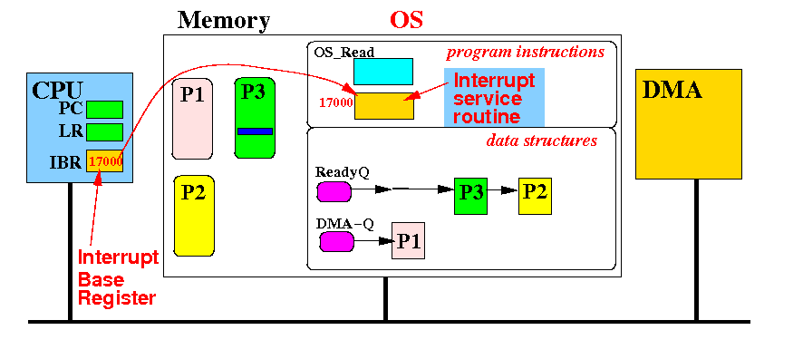
Simplied version:
the IBR register contains
the
address of the
Interrupt Service Routine
(
simplifies identification - see next sets of slides
)
Background: the
Interrupt Service Routine
The Interrupt Service (Sub)Routine = a special function to service the request from a device
Each device will have its own Interrupt Service Routine taylored to process the request from that device
The operation of the
CPU when it
detects an
interrupt request
The CPU is currently executing an instruction (from process P3):
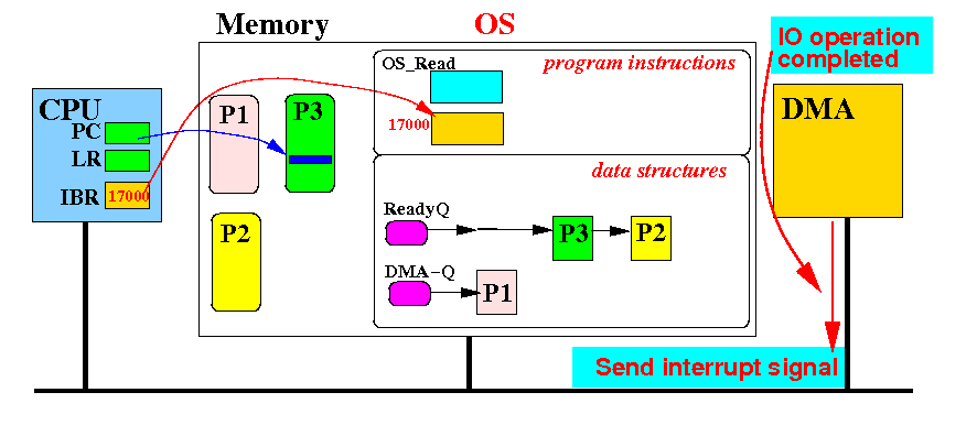
When the DMA finishes the IO operation, it sends an interrupt request signal to the CPU
The operation of the
CPU when it
detects an
interrupt request
When the CPU detects the interrupt request at step 5 (= after executing the current instruction):
The CPU will make a forced subroutine call to the subroutine location at the address in the IBR
The operation of the
CPU when it
detects an
interrupt request
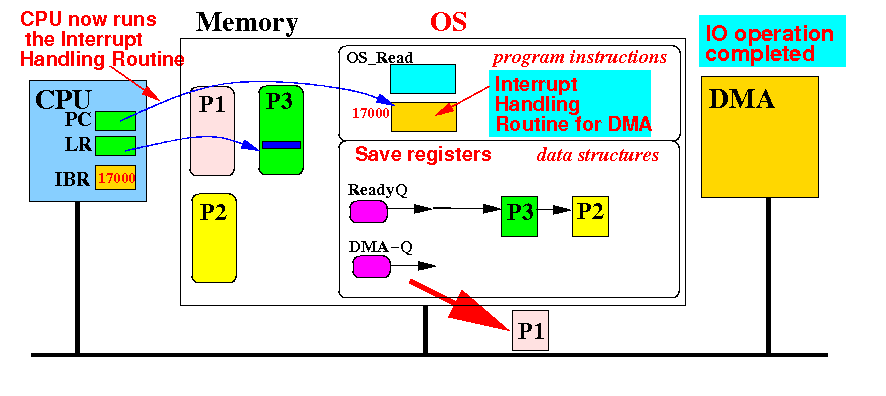
The CPU has saved P3's return address (in LR register) and now runsthe Interrupt Handler:
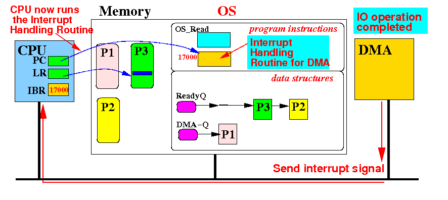
The Interrupt Handling Routine starts running !!! What should it do ??
The operation of the
CPU when it
detects an
interrupt request
Remember what we wanted to achieve when the DMA has completed the IO operation:
The Interrupt Handling Routine is executed to achieve this result !!!
The Interrupt Handling Routine for the
DMA device
To run process P3, the interrupt handler must execute the following code:
   The Interrupt Service Routine for the DMA device:


    // The main task consists of these 2 actions
    (3) Remove the PCB from the DMA device queue

    (4) Insert this PCB at the head of the Read Queue

    (5) Restore the context (register values) using
   	the PCB at the head of the Ready Queue

    (6) Return (mov pc, lr)
|
However: a process (P3) is currently running and must be paused !
The Interrupt Handling Routine for the
DMA device
We must pause the current process first:
   The Interrupt Service Routine for the DMA device:


    (2) Save context from CPU into the PCB
   	at the head of the Ready Queue

    // The main task consists of these 2 actions
    (3) Remove the PCB from the DMA device queue

    (4) Insert this PCB at the head of the Read Queue

    (5) Restore the context (register values) using
   	the PCB at the head of the Ready Queue

    (6) Return (mov pc, lr)
|
Note: the CPU must stop the interrupt signal (or the CPU will keep being "interrupted")
The Interrupt Handling Routine for the
DMA device
We must pause the current process first:
   The Interrupt Service Routine for the DMA device:

    (1) Acknowledge the Interrupt (explained soon)

    (2) Save context from CPU into the PCB
   	at the head of the Ready Queue

    // The main task consists of these 2 actions
    (3) Remove the PCB from the DMA device queue

    (4) Insert this PCB at the head of the Read Queue

    (5) Restore the context (register values) using
   	the PCB at the head of the Ready Queue

    (6) Return (mov pc, lr)
|
This is the interrupt service routine for the IO device !
The effect of the
Interrupt Service Routine for
IO completion by the
DMA
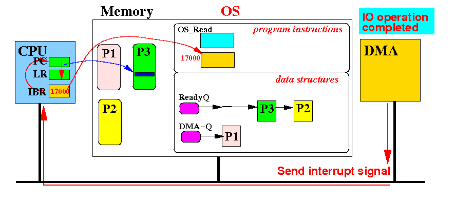
The initial state when the Interrupt Service Routine starts running:
Notice: the DMA is sending out an Interrupt signal
The effect of the
Interrupt Service Routine for
IO completion by the
DMA
(1) Acknowledge the interrupt - the CPU sends out the Interrupt Acknowledge signal:
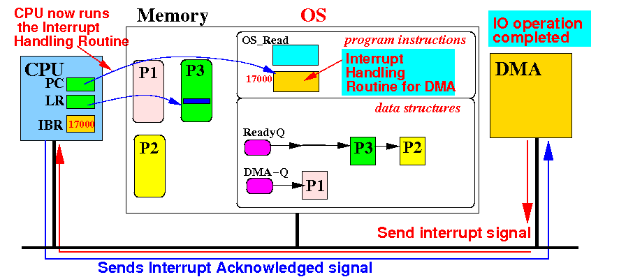
In response, the interrupting device (= DMA) withdraws its interrupt request !
Otherwise, the CPU will detect the (old) interrupt signal again and branch !
The effect of the
Interrupt Service Routine for
IO completion by the
DMA
(2) Save context from CPU into the PCB at the head of the Ready Queue:
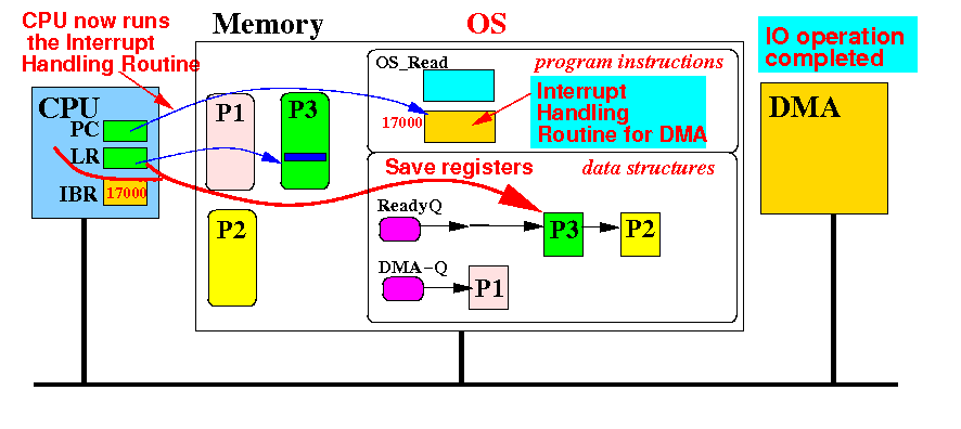
This step enables the Operating System to resume the process P3 (from the paused location)
The effect of the
Interrupt Service Routine for
IO completion by the
DMA
(3) remove PCB from DMA queue and ....
The effect of the
Interrupt Service Routine for
IO completion by the
DMA
(4) insert the PCB at the head of the Ready queue:
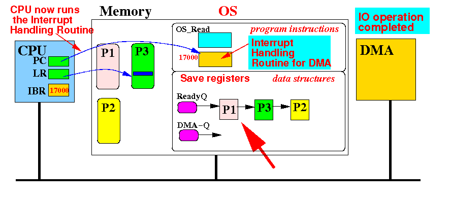
This step makes the process P1 the new current process (in the next step)
The effect of the
Interrupt Service Routine for
IO completion by the
DMA
(5) restore the registers using the values in the first PCB in the Ready queue:
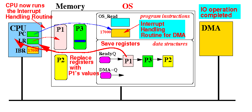
Notice the return address in the LR register will point to an instruction in process P1 !!
The effect of the
Interrupt Service Routine for
IO completion by the
DMA
Result when the Interrupt Service Routine returns: (i.e.: mov pc, lr)
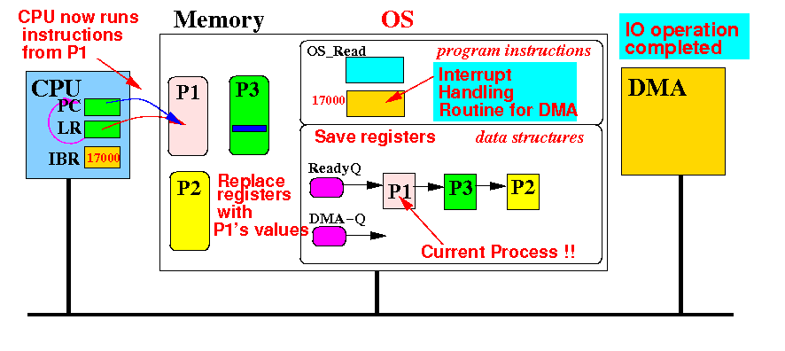
Process P1 will resume its execution !! This is correct because the data has been transfered !!
Summary: Interrupt Service Routine
|