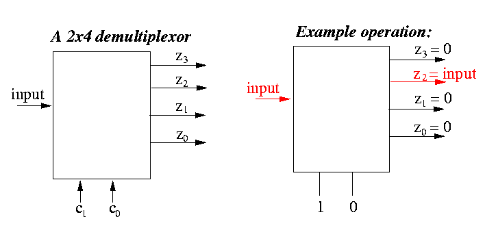
At any time, the input signal is directed (switched) to exactly one of the outputs (and all other outputs are equal to 0) and the output that receves the input signal depends on the current values of the control signals.
The following figure shows schematically what a 2x4 demultiplexor does. The 2x4 decoder has 2 control signals and 4 outputs:


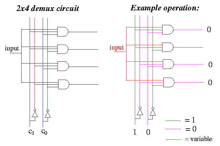
- The construction is very simple and similar to a decoder.
- You connect the inputs of the and-gates to every possible combinations
of the input signals:
- (c1) (c0)
- (c1) (NOT c0)
- (NOT c1) (c0)
- (NOT c1) (NOT c0)
- Then connect the input to all and-gates.
- The filtering is done by the and-gates: exactly one of then will
let the input signal pass.
- The right figure shows that when what happens when the control signals c1 = 1 and c0 = 0. In this case, c1 = 1 and (NOT c0 = 1), so that the second AND gate will receive all 1's as inputs PLUS the input signal that is variable. Only this and gate will let the input signal pass, and all other and-gates will output 0 (input signal is stopped).
/home/cs355001/bin/cs355sim /home/cs355001/demo/circuits/demux |
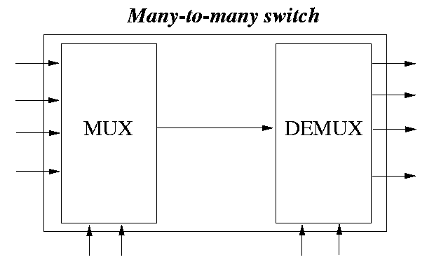
- a many-to-many switch is a device that can make connections between a set of inputs and a set of outputs
- depending on the number of internal connections (and cost) the number of simultaneous connections can range from "1 input to 1 output at a time" to "all inputs to all outputs".
The following figure illustrates this many-to-many switch:

The figure on the right depicts the fact that the second input is connected to the last output.
Note that the unconnected inputs and unconnected outputs will not be active:
- changes in the unconnected inputs will not have any effect on any of the the output signals
- the unconnected outputs will always have a value 0
/home/cs355001/bin/cs355sim /home/cs355001/demo/circuits/mux-demux |
