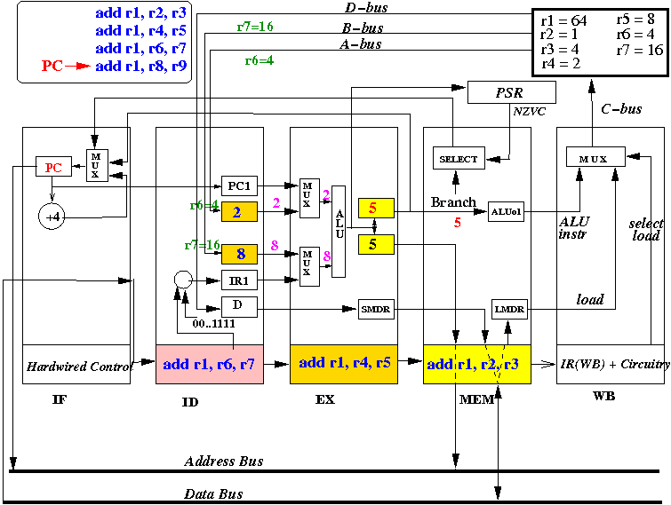
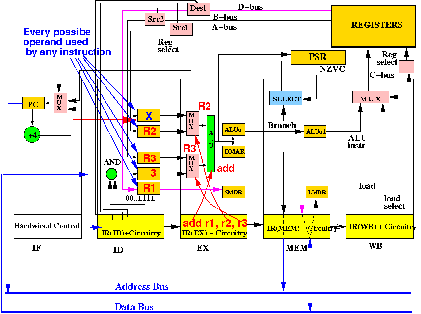
Important difference between a pipelined CPU and a "normal" CPU:

The pipelined CPU executes multiple instructions simultaneously while the "normal" CPU executes one instruction at a time.
|
Consider the following assembler program code fragment:
add r1, r2, r4 // Instruction writes register r1 add r4, r1, r4 // Instruction reads register r1 add r5, r1, r5 add r6, r1, r6 |
The first instruction writes (= updates) the register r1
Then the next 3 instruction reads (= uses) the register r1
We call this instruction sequence: read-after-write (because we read a register immediately after writing the register)
The read-after-write construct will cause instruction execution errors in the basic pipelined CPU (that we must solve !!!)
The first moment that the pipelined CPU uses operands of an instruction is in the EX stage:

Therefore: the correct operands must be available when an instruction is inside the EX stage !!!
I will explain the read-after-write data hazard using a series of diagrams:

This is the initial state: the pipelined CPU has fetched the instruction add r1,r2,r3.
Start of cycle 2: ID fetches operands for add r1,r2,r3 and IF fetches add r4,r1,r4

End of cycle 2: R2, R3 for add r1,r2,r3 fetched and next instruction add r4,r1,r4 fetched

Note: the correct execution of instruction add r4,r1,r4 must use r1=192+48=240 !!!
Start 3: EX computes R2+R3=240, ID fetches R4=1,R1=12 and IF fetches add r5,r1,r5

Notice the result of add r1,r2,r3 (= 240) is not yet available in register R1 !!!
End 3: R1+R2 stored in ALUo, R4, (old)R1 fetched and add r5,r1,r5 fetched

Note: the EX stage will execute add r4,r1,r4 using a wrong value (12) for R1 !!!
Start 4: MEM does no op, EX computes R4+R1=13 !!, ID fetches R5=2,R1=12 and IF fetches

Notice the result of add r1,r2,r3 (= 240) is still not available in register R1 !!!
End 4: R1+R2 ⇒ ALUo1, R4+(old)R1 ⇒ ALUo, R5, (old)R1 fetched and add r6,.. fetched

Note: the EX stage will also execute add r5,r1,r5 using a wrong value (12) for R1 !!!
|
Start 5: WB write R1, MEM no op, EX comp: R5+R1=14 !!, ID fetch R5,R1 and IF fetch

Notice the result of add r1,r2,r3 (= 240) is not yet available in register R1... will change !
Mid cycle 5: WB completes the writing of R1:

Notice the result of add r1,r2,r3 (= 240) is now available in register R1... and being fetched !
Later in cycle 5: The new value in register R1 arrives at the input of the special register

The ID stage can fetch the correct value for source register R1 !!!
End 5: R2+R3 ⇒ R1, R4+(old)R1 ⇒ ALUo1, R5+(old)R1 ⇒ ALUo, R5,(new)R1 fetched

Conclussion: 2 instructions following add r1,r2,r3 is unable to fetch the updated R1 value
|
