The LOAD instruction encoding format (meaning of the bits in the instruction):

I will only discuss the register as 2nd source operand (the constant operand is similar)
Clock cycle 1: The IF stage fetches the instruction into the IR(ID) register

I have include the instruction code in binary
Start of clock cycle 2: the ID stage fetch all possible source operands

End of clock cycle 2: all source operands are fetched - but only R2 and R3 will be used

Notice: the instruction is moved into the IR(EX) register
Start of clock cycle 3: the EX stage operates on the correct source operands

The EX stage computes the memory address R2+R3 used by ldr r1,[r2,r3] !!!
End of clock cycle 3: the result is stored in ALU Output and the Data Mem Addr registers

Notice: the instruction is moved into the IR(MEM) register
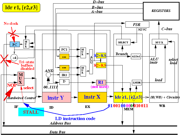
Start of clock cycle 4: the MEM stage executes the ldr r1, [r2,r3]

The MEM stage sends a READ request and the address R2+R3 on the system bus. WAIT !!!
Start of clock cycle 4: notice that the IF stage also wants to use the system bus

The MEM stage has priority over the IF stage !!! The IF stage must be stopped (paused) !
Solution: when MEM stage detects a ldr instruction, it sends a STALL signal to the IF stage

The STALL signla will (1) disable the clock signal in the IF stage (2) send a NOP instr to IR(ID)
The MEM stage executes the ldr instruction and sends a READ request on the system bus:

In response, the memory sends back the data requested on the data bus
End of clock cycle 4: the memory data (1234) is stored in the Load Mem data register

Notice: a harmless NOP (no-op or "do nothing") instruction is inserted into the IR(ID) register
Start 5: the ldr instr causes the WB stage to select LMDR as input and update the register R1

End of clock cycle 5: the result 1234 is stored in the register R1

Notice: the instruction has been into the discarded !! (no longer needed !!!)
|