Sharing the
system bus
The system bus is a information transport conduit between any 2 components in a computer:
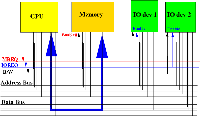
(1) for sending data between CPU and memory
Sharing the
system bus
The system bus is a information transport conduit between any 2 components in a computer:
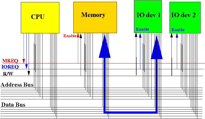
(2) for sending data between an IO device (e.g., disk) and memory
Sharing the
system bus
Important: at most ONE device can transmit data on the system (data) bus at any time:
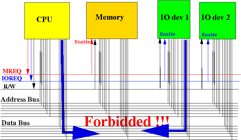
Multiple transmitting devices will cause a short circuit condition !!!
Sharing the
system bus:
arbitration
Arbitration = process in which competing master devices decide on which device gets to use the system bus
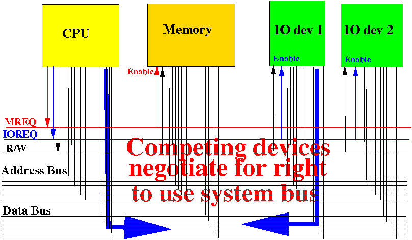
The winning device in the arbitration process will become the master device to use the system bus
Review:
bus protocol
|
Bus utilization period = time when the system bus is used for data transfer
Bus cycle
|
Overlap execution of the arbitration and utilization cycles
Notice that the pins used for bus arbitration are separate from those used for bus utilization:
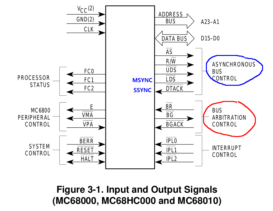
Therefore: the
arbitration operation can
run concurrently with
the data transfer operation
on the system bus !!!
(It's like having a separate lane
of traffic)
Overlap execution of the arbitration and utilization cycles
The bus arbitration periods and bus utilization periods will occur in this manner when run concurrently:
The competing device that wins in the previous bus arbitration period will get to use the system bus in the following bus utilization period
Next: we study the circuitry used to perform arbitration
2 types of
bus arbitration techniques
|
An early days
(simple) centralized bus arbiter circuit: the
daisy chain
The daisy chain arbiter circuitry is as follows:
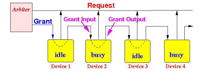
A device has
3 signals:
Grant Input =
1 means the
device may
use the system bus next,
0 means:
not its turn
Request =
1 means the
device
wants to
use the system bus next,
0 means:
don't need it
Grant output =
1 means the
next device
may
use the system bus next,
0 means:
cannot
An early days
(simple) centralized bus arbiter circuit: the
daisy chain
The idle state:
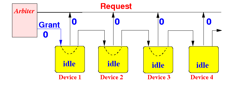
When all devices do not want to use the system bus, the Grant signal = 0
An early days
(simple) centralized bus arbiter circuit: the
daisy chain
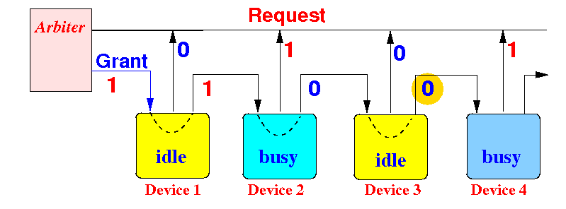
The busy state:
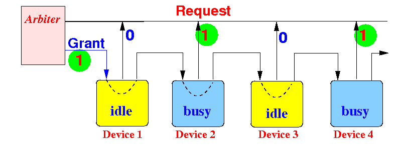
When at least 1 device wants to use the system bus, the Grant signal = 1
An early days
(simple) centralized bus arbiter circuit: the
daisy chain
Grant processing by an idle device:
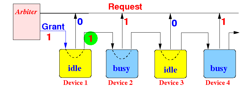
An idle device that receives Grant=1 will forward the grant downstream.
An early days
(simple) centralized bus arbiter circuit: the
daisy chain
Grant processing by an busy device:
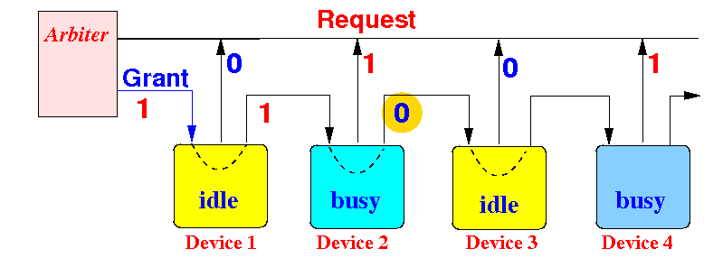
An busy device that receives Grant=1 will remove the grant and declare itself the winner.
An early days
(simple) centralized bus arbiter circuit: the
daisy chain
Voided-grant processing by an idle device:
An idle device that receives Grant=0 will forward the Grand=0 downstream.
An early days
(simple) centralized bus arbiter circuit: the
daisy chain
Voided-grant processing by an busy device:
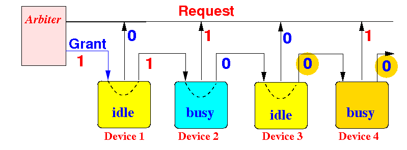
An busy device that receives Grant=0 will forward the Grant=0 and declare itself a loser.
Result: device 2 is the winner and will use the system bus in the next bus cycle !
An early days
(simple) centralized bus arbiter circuit: the
daisy chain
The daisy chain defines a priority ordering ("pecking order"):
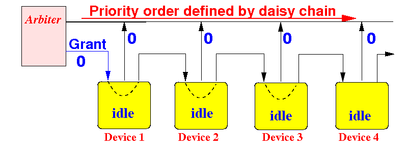
The daisy chain technique is simple, but inflexible
Wait, aren't there
some outputs
connected together ?
The astute student will have noticed that some outputs have been connected together:
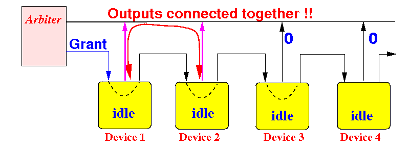
For this reason, the Request outputs of the devices must use a special output circuit called: "Open Collector" output
What is so special about an
Open Collector output ?
Ordinary circuit outputs have low impendance (= resistance) that achieve very fast operation speed:
Notice the AND gate above does not use a resistor between +Vcc and the output OUT
What is so special about an
Open Collector output ?
A Open Collector output have high impendance (= resistance) resulting in a slower operation speed:
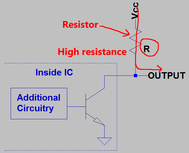
Notice the (large) resistor R component between Vcc and the output OUTPUT
The resistance prevents a short-circuit condition, but will also slow down the output operation
What doe sit mean
by "slower" circuit operation ???
A fast circuit will update a change in output value faster (= shorter time)
A open collector output will reach the stable value in a larger amount of time
Centralized arbiter circuit design
Nowadays, the centralized arbiter circuit looks like this:
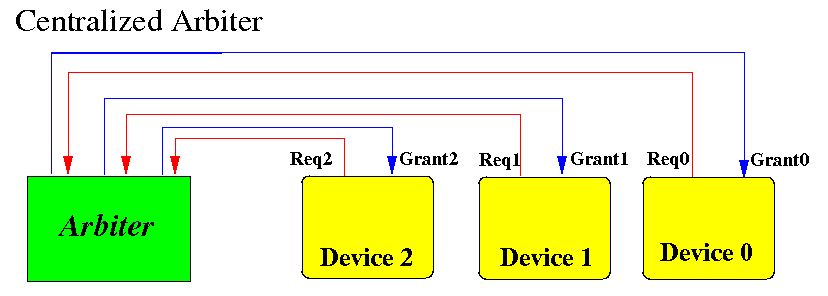
The arbiter circuit will define a priority ordering to grant the bus request to a unique device
Centralized arbiter circuit design
A simple static priority assignment can be easily designed using a logic table:
The logic table for the priority order: Device 2 > Device 1 > Device 0
   Req2  Req1   Req0  |  Grant2  Grant2   Grant0
 ---------------------+----------------------------
    0     0      0    |    0       0        0
    0     0      1    |    0       0        1
    0     1      0    |    0       1        0
    0     1      1    |    0       1        0
    1     0      0    |    1       0        0
    1     0      1    |    1       0        0
    1     1      0    |    1       0        0
    1     1      1    |    1       0        0
|
Problem with a
centralized arbiter (circuit)
When the arbiter circuit fails, the whole system will stop:
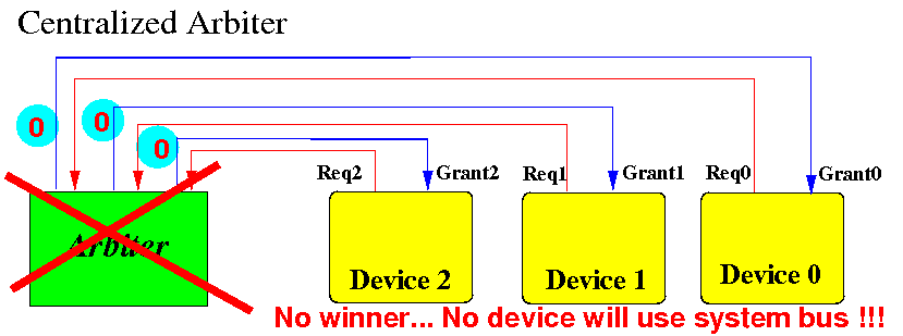
No device will become the the next master device to use the system bus !!!
Distributed arbiter circuit design
A distributed
arbitration circuit
can be
designed as
follows:
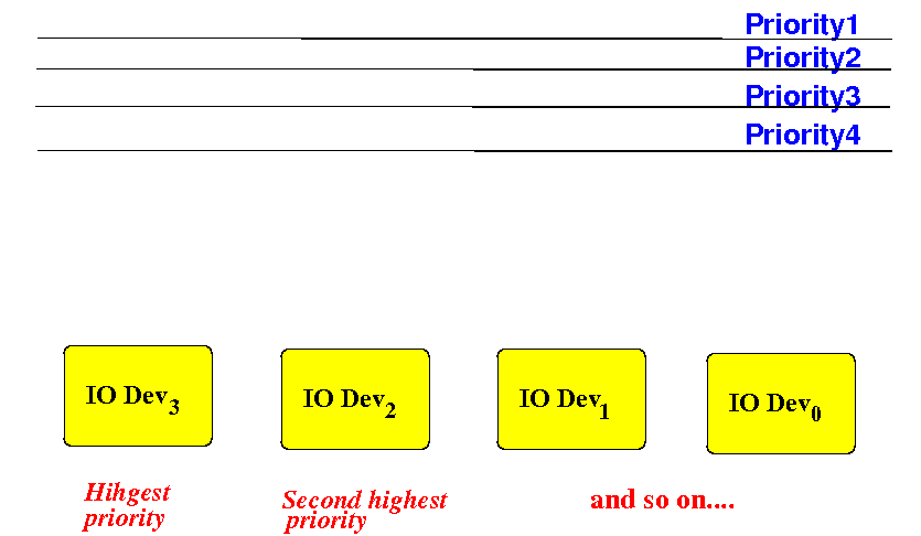
The Priority1 wire has the highest priority and Priority4 the lowest
Distributed arbiter circuit design
The highest priority device
receives a grant whenever
it makes a request:
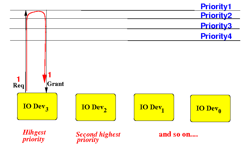
When Req=1, then Grant=1 and when Req=0, then Grant=0
Distributed arbiter circuit design
The 2nd highest priority device
receives a grant
only when
highest priority device
is not making a request:
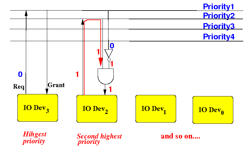
When it's Req=1 and higher priority request=0, then Grant=1, otherwise: Grant=0
Distributed arbiter circuit design
The 3rd highest priority device receives a grant only when both higher priority device are not making requests:
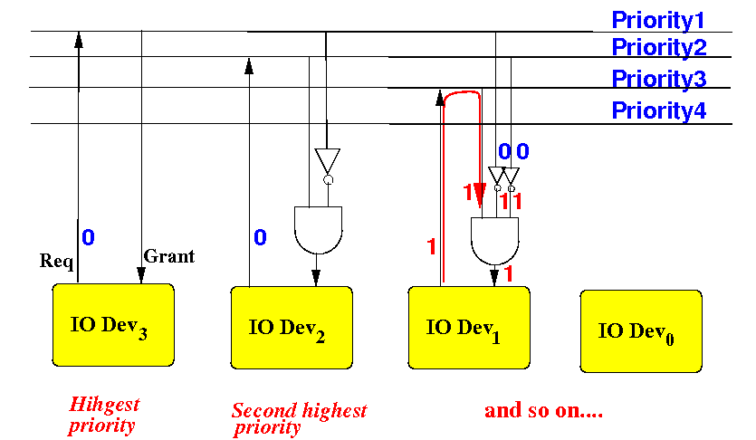
When it's Req=1 and all higher priority request=0, then Grant=1, otherwise: Grant=0
Advantage of
a distributed
arbiter
A failure will
not cause
the system to
stop operating:
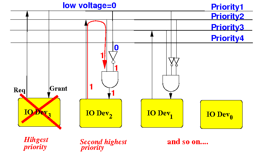
When a device fails, the arbitration process will continue to operate