Example: controlling the chronological order
of events in
the instruction execution cycle
Suppose the next machine code fetched is 00000000000100010110000000000000 (add r1,r0,r6):
(Ignore the blue colored bits, they are not used to control the CPU operation in this instruction)
Example: controlling the chronological order
of events in
the instruction execution cycle
The first clocking event is the Phase 1 clock signal:
The Phase 1 clock signal will update the IR with the new machine code
Example: controlling the chronological order
of events in
the instruction execution cycle
Result:
The next clocking event is the Phase 2 clock signal...
Example: controlling the chronological order
of events in
the instruction execution cycle
The new instruction code is sending new selection signal when Phase 2 clock signal occurs:
The Phase 2 clock signal will update the A & B-buffers with the values in registers R0 and R6 !
Example: controlling the chronological order
of events in
the instruction execution cycle
Result: the operands (R0 and R6) have been fetched !!!
The next clocking event is the Phase 3 clock signal...
Example: controlling the chronological order
of events in
the instruction execution cycle
During Phase 3, the ALU circuitry will (take time) to compute the sum on the input operands:
Computational circuits have large delay times (e.g., ripple carry adder !!)
Example: controlling the chronological order
of events in
the instruction execution cycle
Result: at the end of Phase 3 period, the result R0+R6 is on the C-bus:
The next clocking event is the Phase 4 clock signal...
Example: controlling the chronological order
of events in
the instruction execution cycle
The Phase 4 clock will update the destination register (R1) with the input value R0+r6:
The instruction cycle is completed !!!
Example: controlling the chronological order
of events in
the instruction execution cycle
Result: the CPU has execution the instruction add r1,r0,r6:
And the instruction execution cycle will repeat again !!!
Example 2: controlling the chronological order
of events in
the instruction execution cycle
Example: the event sequencing in a str machine instruction
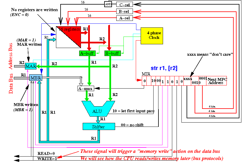
We will now look at the event sequences when the CPU executes a str instruction (it's similar)
Example 2: controlling the chronological order
of events in
the instruction execution cycle
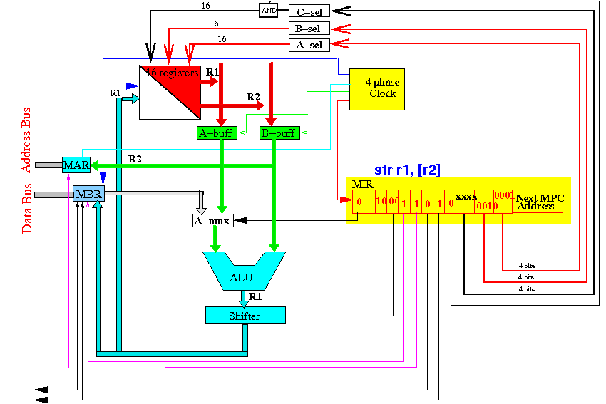
Suppose the next machine code fetched is 10010001101000000010000100000000 (str r1,[r2]):
(Ignore the blue colored bits, they are not used to control the CPU operation in this instruction)
Example 2: controlling the chronological order
of events in
the instruction execution cycle
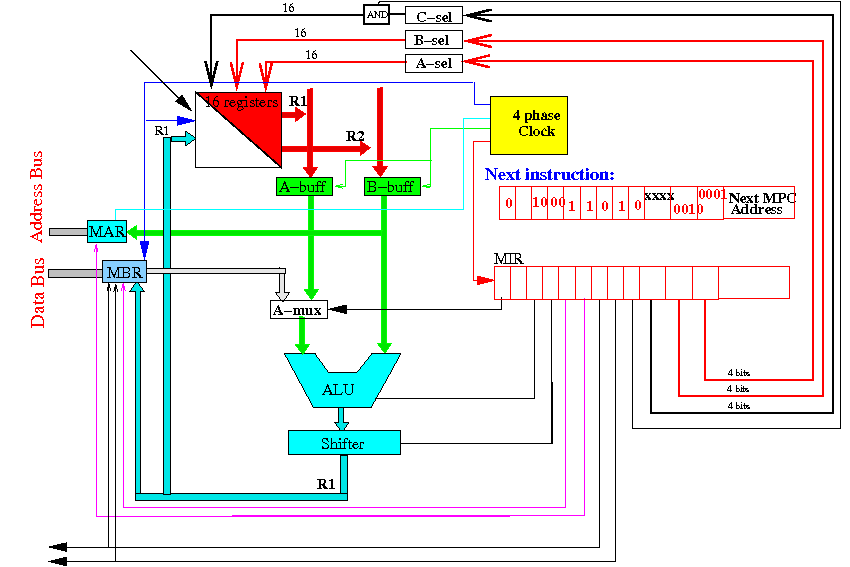
The first clocking event is the Phase 1 clock signal:
The Phase 1 clock signal will update the IR with the new machine code
Example 2: controlling the chronological order
of events in
the instruction execution cycle
Result:
The next clocking event is the Phase 2 clock signal...
Example 2: controlling the chronological order
of events in
the instruction execution cycle
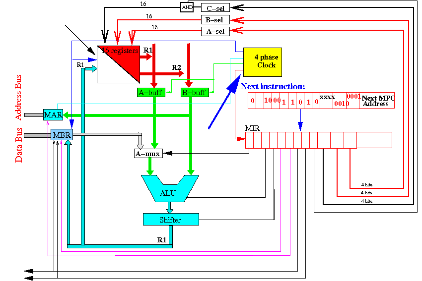
The new instruction code is sending new selection signal when Phase 2 clock signal occurs:
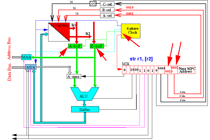
The Phase 2 clock signal will update the A & B-buffers with the values in registers R1 and R2 !
Example 2: controlling the chronological order
of events in
the instruction execution cycle
Result: the operands (R1 and R2) have been fetched !!!
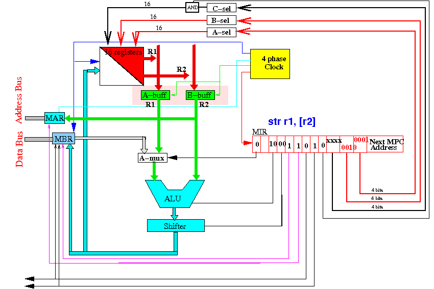
The next clocking event is the Phase 3 clock signal...
Example 2: controlling the chronological order
of events in
the instruction execution cycle
During Phase 3, the ALU + Shifter will compute the R1 and MAR is updated:
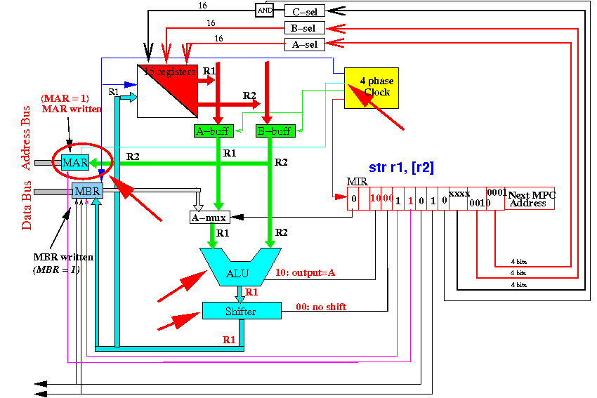
The MAR now has the address value (= the value in register R2 !!)
Example 2: controlling the chronological order
of events in
the instruction execution cycle
Result: at the end of Phase 3 period, the R2 is sent on the address bus:
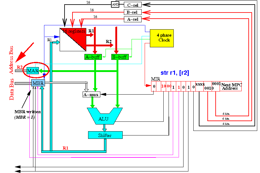
The next clocking event is the Phase 4 clock signal...
Example 2: controlling the chronological order
of events in
the instruction execution cycle
The Phase 4 clock will update the MDR register with the input value R1:
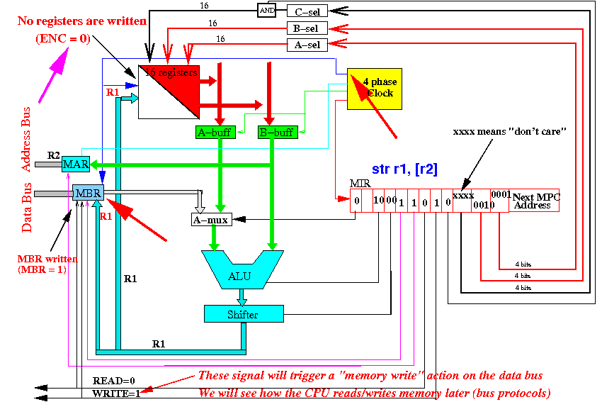
The instruction cycle is completed !!!
Example 2: controlling the chronological order
of events in
the instruction execution cycle
Result: the CPU has executed the instruction str r1,[r2]:
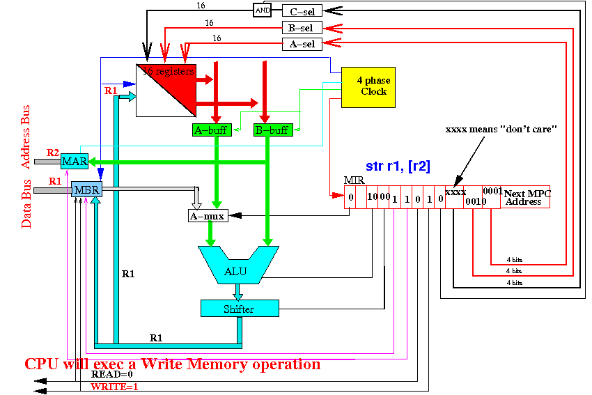
This will trigger the communication subsystem in the CPU to run a "bus protocol" before starting a new instruction execution cycle
DEMO
|
Summary
|