Developing the simple CPU
- purpose of
the datapath
|
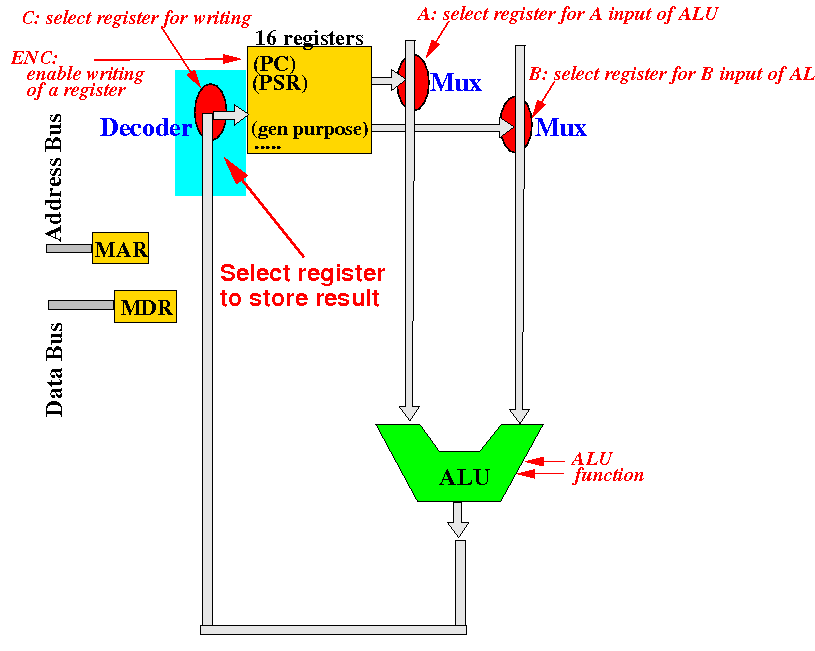
The parts of the
datapath that we
have discussed so far
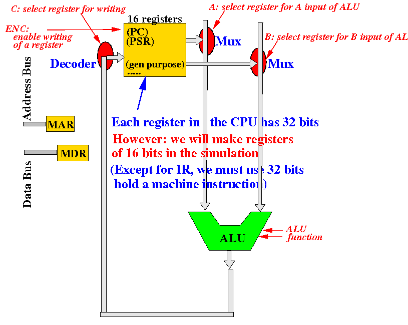
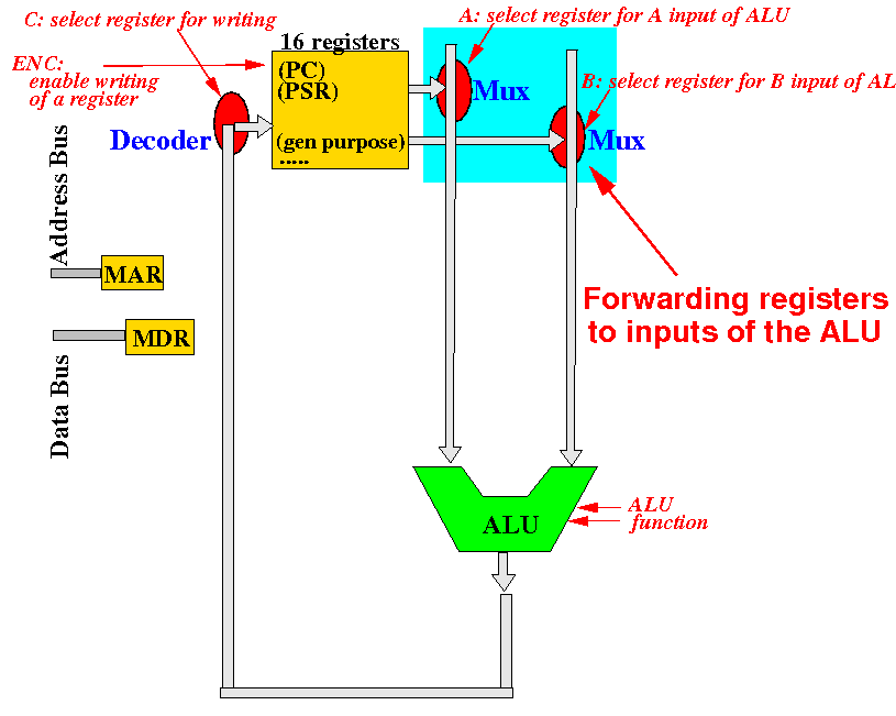
(1) How to
forward source
registers to the
ALU
(2) How to
select a
register to
update with the
output of the
ALU
The parts of the
datapath that we
have discussed so far
(1) How to
forward source
registers to the
ALU
The parts of the
datapath that we
have discussed so far
(1) How to
forward source
registers to the
ALU
The parts of the
datapath that we
have discussed so far
(2) How to
select a
register to
update with the
output of the
ALU
The parts of the
datapath that we
have discussed so far
(2) How to
select a
register to
update with the
output of the
ALU
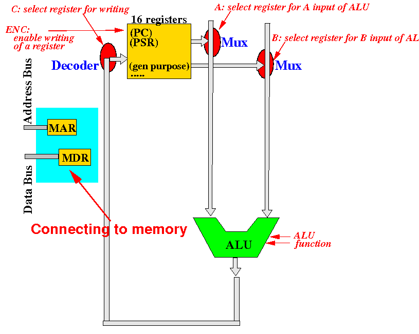
The parts of the
datapath that we
have discussed so far
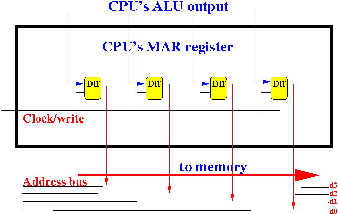
(3) How to
connect the
MAR register to the
address bus
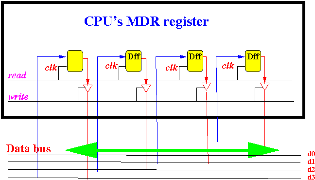
(4) How to
connect the
MDR register to the
data bus
The parts of the
datapath that we
have discussed so far
(3) How to
connect the
MAR register to the
address bus
(4) How to
connect the
MDR register to the
data bus
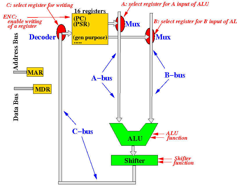
Nomenclature: A-bus, B-bus and C-bus
of the Datapath
For convenience sake, we call the following buses: the A-bus, the B-bus and the C-bus:
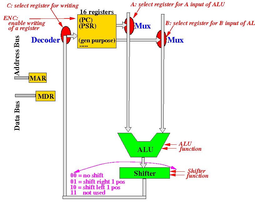
Adding support for shift operation
(1) We first add a shifter circuit after the ALU to shift the ALU output left or right:
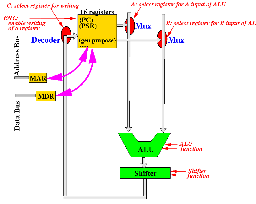
Assesing the CPU:
no pathway to
transfer info between
registers and
MAR & MDR
Notice that: there are no paths connecting the MAR and MDR registers and the other CPU registers:
Adding more connections - review:
rules on connecting circuit components
Review: you cannot connect 2 outputs with each other
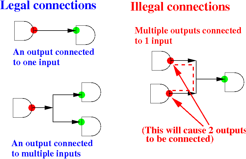
Note: later in the course, you will learn about a "high impedance" output circuit that can be connected together.
Add pathway to send
value in a register to the
MAR
(2) We connect the B-bus to the inputs of the MDR:
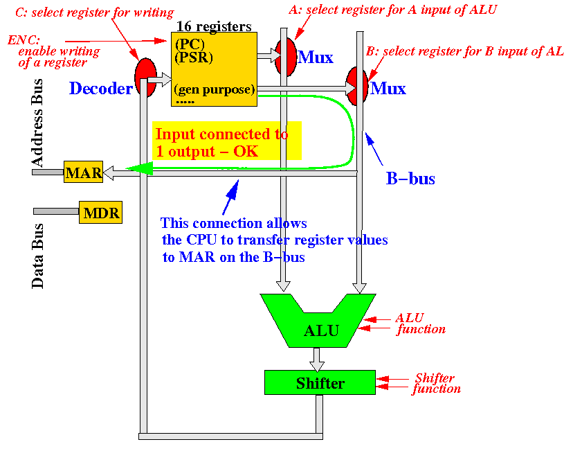
This will allow the CPU to transfer an address from a register to the MAR in the ldr and str instructions
Add pathway to send a
value in a register to the
MDR
(3) We connect the C-bus to the inputs of the MDR:
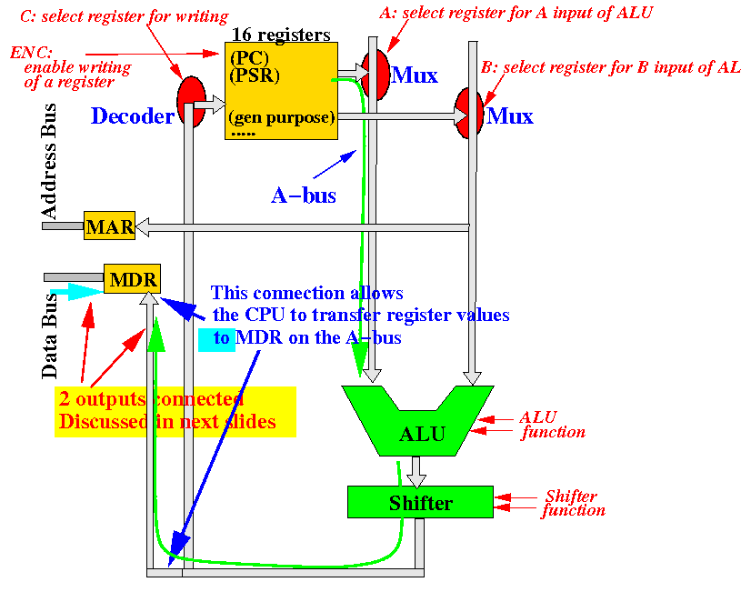
This will allow the CPU to transfer data from a register to the MDR in the str instructions
Add pathway to send a
value in the MDR to a
register
(4) We connect the MDR to the inputs of the ALU:
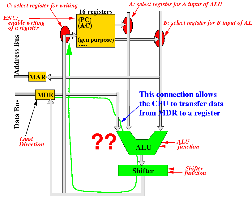
This will allow the CPU to transfer data from the MDR to a register in the ldr instructions
Add pathway to send a
value in the MDR to a
register
(4) Unfortunately, we cannot connect the MDR outputs directly to the ALU inputs:
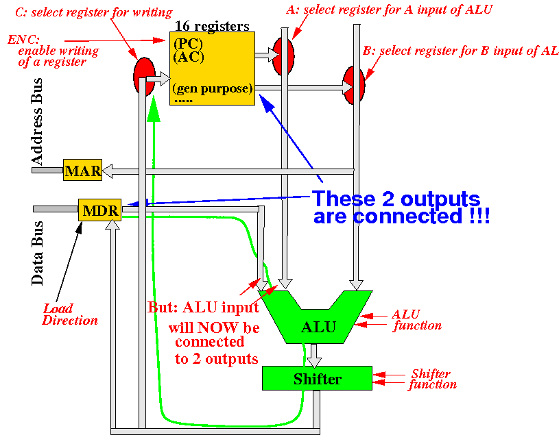
Because this will connect the outputs of the MDR to the outputs of a register !
Add pathway to send a
value in the MDR to a
register
(4) Solution: we use a 2 way multiplexor to switch between the register outputs and the MDR outputs:
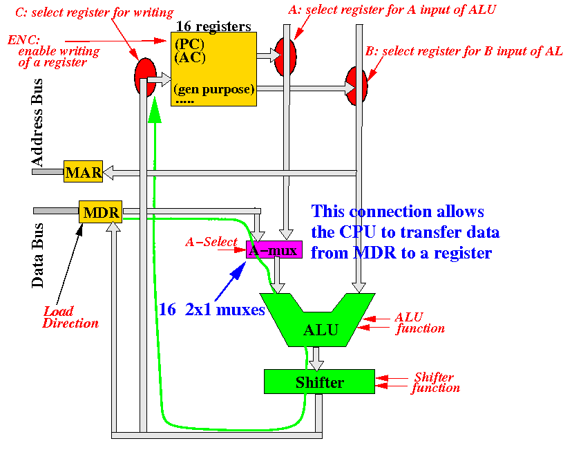
The A-Select signal is used to choose between the A-bus data and the MDR data
Registers are added
to buffer the
input values for the
ALU to
simplify timing
(5) The registers A-buffer and B-buffer are added on the A-bus and B-bus to simplify timing:
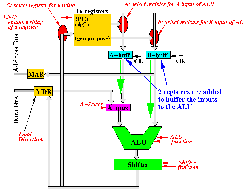
The timing problem in the event sequencing problem will be discussed later...
Note that we need write signals for the
MAR and the
MDR registers
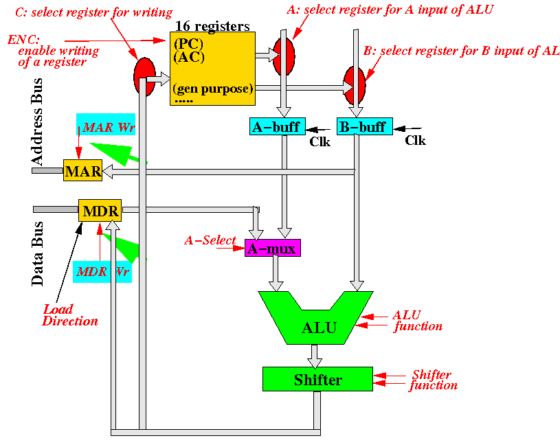
Note: all registers (MAR, MBR, A-buffer and B-buffer) has an associated write signal
Review:
catagories of machine instructions
Catagory 1: Move: mov, movw, movt Arithmetic: add, sub, mul, cmp Branching: b, bgt, bge, blt, blt, beq, bne Catagory 2: Load: ldr r1, [r2] Store: str r1, [r2] |
I will now show you the pathways in the CPU used to transfer data in the execution of each of these types instructions
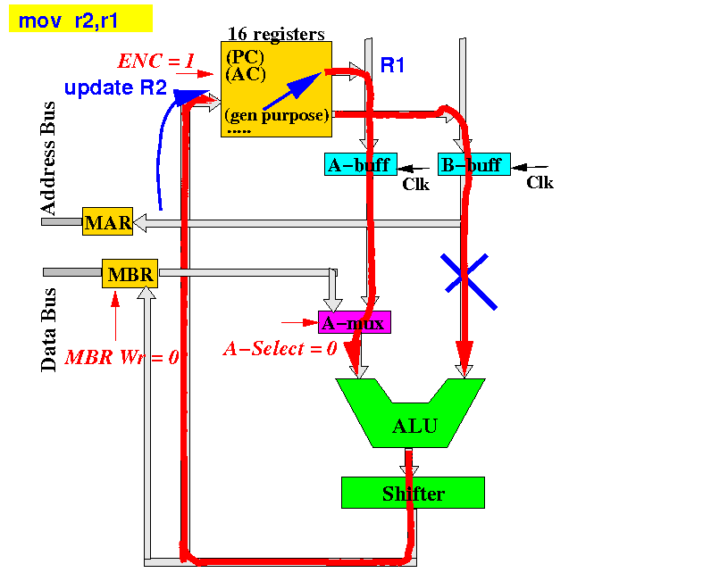
Pathway inside the CPU used to execute a
computation-type instruction
The mov, add/sub/... and branch instructions uses this pathway:
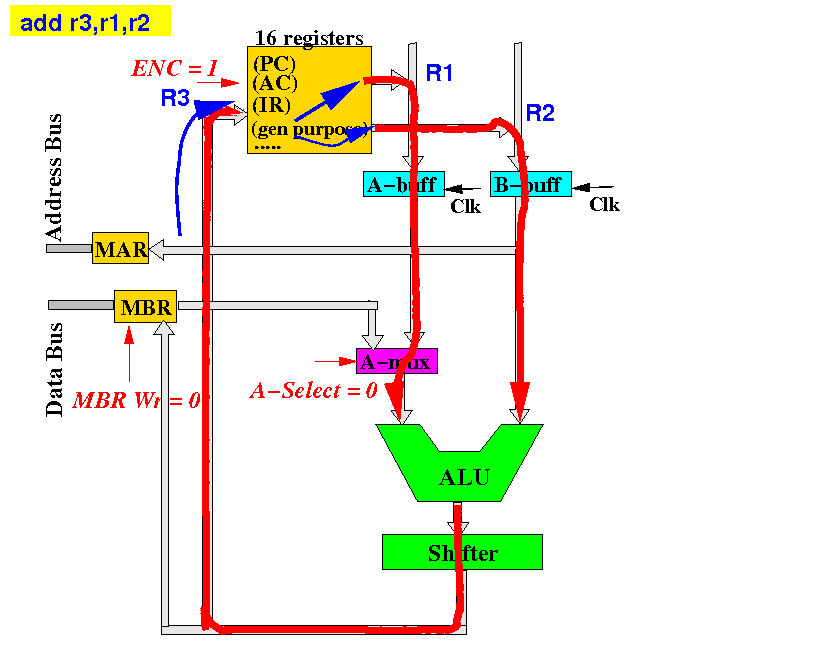
Pathway inside the CPU used to execute a
computation-type instruction
The mov, add/sub/... and branch instructions uses this pathway:
Pathway inside the CPU used to execute a
computation-type instruction
The mov, add/sub/... and branch instructions uses this pathway:
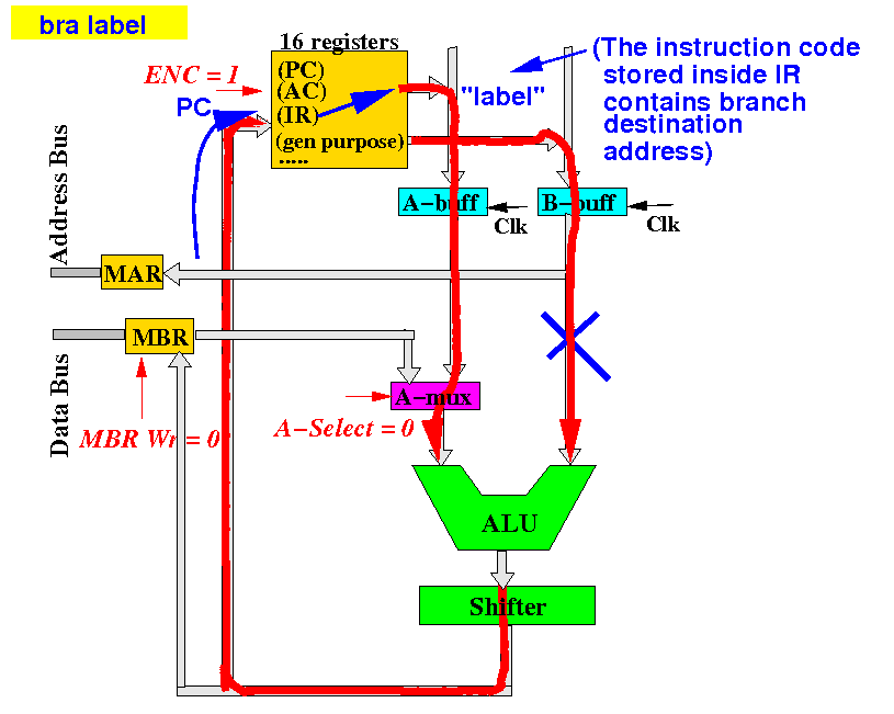
The only difference is the branch instruction updates the Program Counter PC
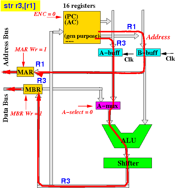
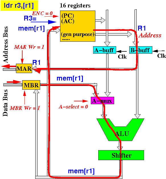
Pathway inside the CPU used to execute a
memory-typed instruction
A ldr instruction uses this pathway:
Pathway inside the CPU used to execute a
memory-typed instruction
A str instruction uses this pathway: