Example of independent stages:
Finite State Machines (FSM)
|
The implementation of a FSM in digital circuit will require the use of D-flipflops (instead of D-latches)
Example of a FSM
The following FSM represents the computational model to recognize all strings of the form: a(b*)c
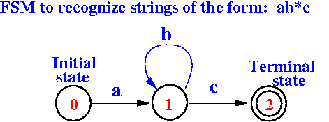
Strings such as ac, abc, abbc, etc will cause the FSM to reach the terminal (= accept) state
(I think FSM was covered in CS244...)
Time-controlled transitions
|
In the next few slides, we will build a simple time-controlled FSM as an introduction on how a CPU operates...
FSM of a traffic (stop) light
I found this FSM diagram for a traffic light on the Web:
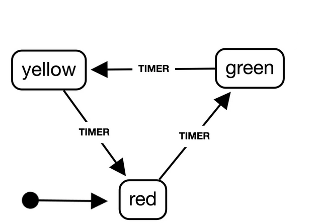
This FSM models the normal (operational) behavior of a stop light...
FSM of a traffic (stop) light - RE-DRAWN
I have re-drawn the FSM state transition diagram:
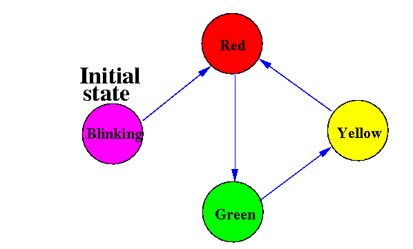
We will show the initial state (= stop light not ready) as blinking (flashing) stop lights...
FSM of a more complex traffic (stop) light
To make the FSM more like a computing machine, we will model a more complex traffic (stop) light that can detect errors:
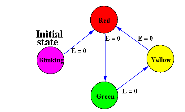
The signal "E" is
a self-diagnosis condition
E=0 means:
no error detected
When no error (i.e.: E=0) the state transitions are as before.
FSM of a more complex traffic (stop) light
To make the FSM more like a computing machine, we will model a more complex traffic (stop) light that can detect errors:

The signal "E" is
a self-diagnosis condition
E=1 means:
an error has been detected
When in error (i.e.: E=1) the FSM will always go to the initial state.
Constructing a FSM with
digital circuits
|
The FSM state transition diagram using the chosen representation code
The FSM's state transition diagram was:
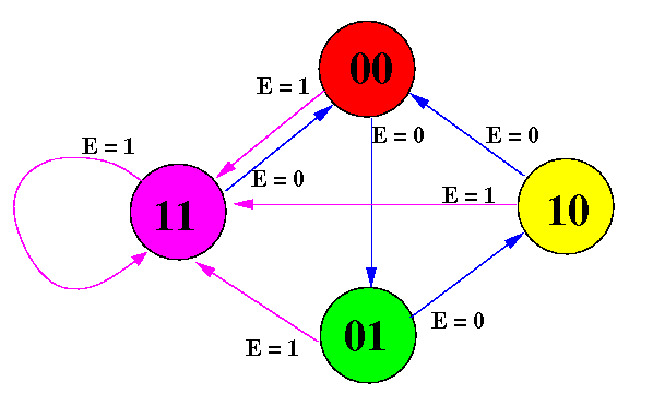
The FSM state transition diagram using the chosen representation code
The FSM's state transition diagram using the assigned numbering is:
How to design a
FSM using
digital circuits
Facts to help you understand the design process:
|
How to design a
FSM using
digital circuits
Facts to help you understand the design process:
|
How to design a
FSM using
digital circuits
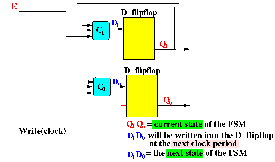
We start with the 2 D-flip flops used to remember the current state of the FSM:
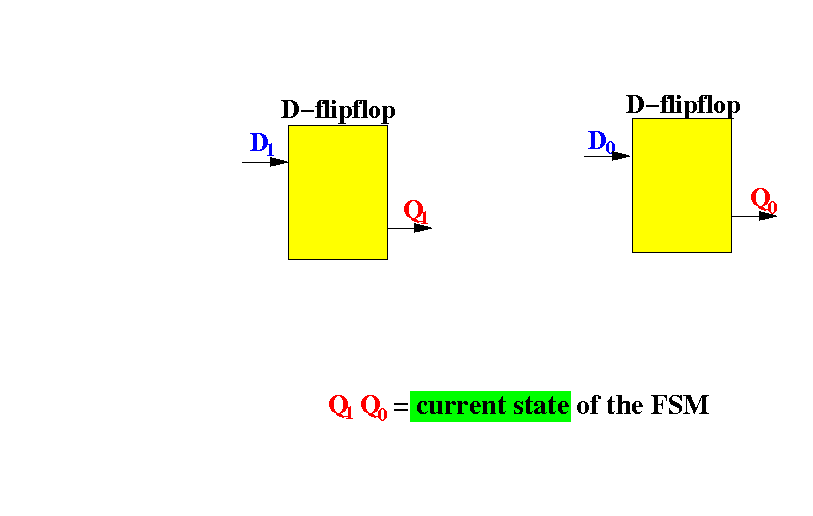
The output of the flip flops are called Q1 and Q0 to tell them apart.
How to design a
FSM using
digital circuits
The D-flip flops are controlled (= written) by the same clock signal:
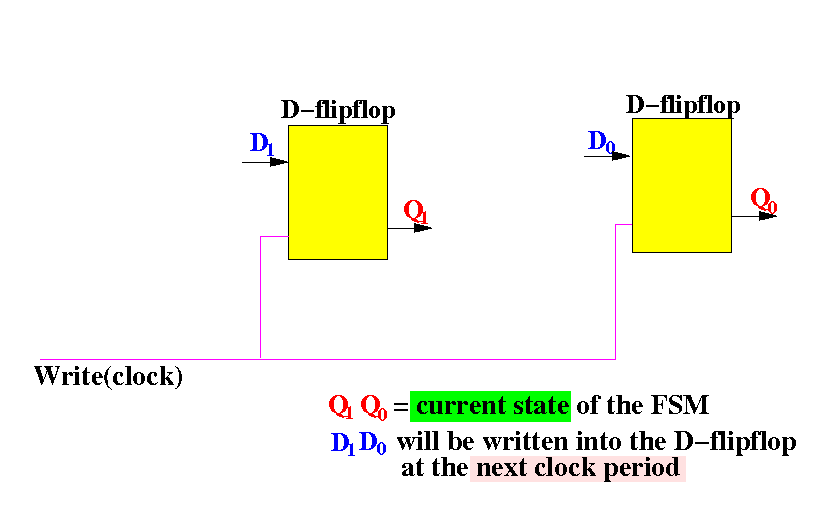
As you have learned: the input Di will be written to output Qi by the clock signal
How to design a
FSM using
digital circuits
The FSM will make a state transition in every clock period. Therefore:
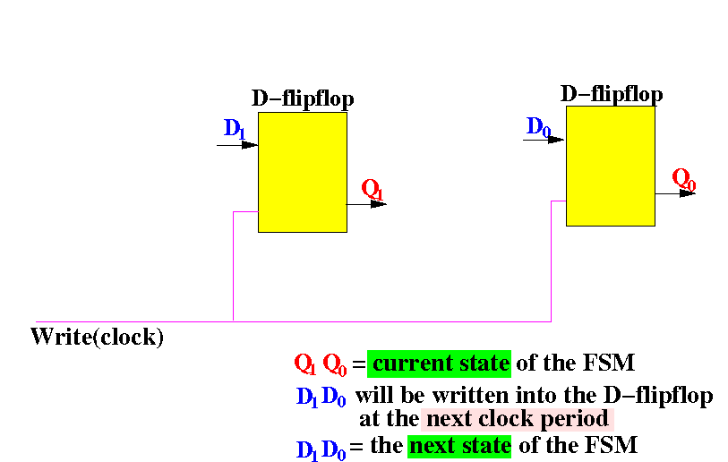
The input D1D1 will be written to output Q1Q1 and therefore, the next state = D1D1
How to design a
FSM using
digital circuits
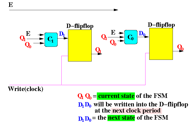
We must compute the correct values for D1 and D0:
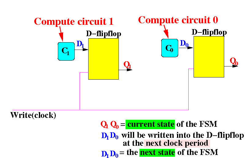
The next state D1D0 depends on: (1) the current state and the (2) error condition !
How to design a
FSM using
digital circuits
Schematically:
How to design a
FSM using
digital circuits
Drawn out with connecting lines:
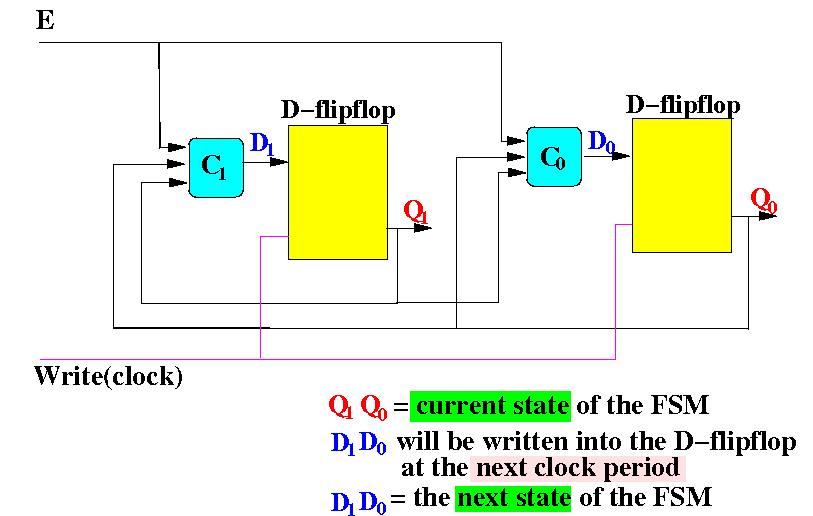
Remaining task: design (and construct) the (computation) circuits C1 and C0
How to design a
FSM using
digital circuits
The FSM state transition diagram of the stop light:
  Error  Current state      Next state
    E       Q1    Q0     |   D1   D0
 ------------------------+---------------
    0       0     0      |
    0       0     1      |
    0       1     0      |
    0       1     1      |
    1       0     0      |
    1       0     1      |
    1       1     0      |
    1       1     1      |
|
How to design a
FSM using
digital circuits
The FSM state transition diagram of the stop light:
  Error  Current state      Next state
    E       Q1    Q0     |   D1   D0
 ------------------------+---------------
    0       0     0      |   0    1   (red → green)
    0       0     1      |
    0       1     0      |
    0       1     1      |
    1       0     0      |
    1       0     1      |
    1       1     0      |
    1       1     1      |
|
How to design a
FSM using
digital circuits
The FSM state transition diagram of the stop light:
  Error  Current state      Next state
    E       Q1    Q0     |   D1   D0
 ------------------------+---------------
    0       0     0      |   0    1
    0       0     1      |   1    0   (green → yellow)
    0       1     0      |
    0       1     1      |
    1       0     0      |
    1       0     1      |
    1       1     0      |
    1       1     1      |
|
How to design a
FSM using
digital circuits
The FSM state transition diagram of the stop light:
  Error  Current state      Next state
    E       Q1    Q0     |   D1   D0
 ------------------------+---------------
    0       0     0      |   0    1
    0       0     1      |   1    0
    0       1     0      |   0    0   (yellow → red)
    0       1     1      |
    1       0     0      |
    1       0     1      |
    1       1     0      |
    1       1     1      |
|
How to design a
FSM using
digital circuits
The FSM state transition diagram of the stop light:
  Error  Current state      Next state
    E       Q1    Q0     |   D1   D0
 ------------------------+---------------
    0       0     0      |   0    1
    0       0     1      |   1    0
    0       1     0      |   0    0
    0       1     1      |   0    0   (flashing (fixed) → red)
    1       0     0      |
    1       0     1      |
    1       1     0      |
    1       1     1      |
|
How to design a
FSM using
digital circuits
The FSM state transition diagram of the stop light:
  Error  Current state      Next state
    E       Q1    Q0     |   D1   D0
 ------------------------+---------------
    0       0     0      |   0    1
    0       0     1      |   1    0
    0       1     0      |   0    0
    0       1     1      |   0    0
    1       0     0      |   1    1 (When error, goto state 11)
    1       0     1      |   1    1
    1       1     0      |   1    1
    1       1     1      |   1    1
|
How to design a
FSM using
digital circuits
Designing the compute circuits C1 and C0:
  Error  Current state      Next state
    E       Q1    Q0     |   D1   D0
 ------------------------+---------------
    0       0     0      |   0    1
    0       0     1      |   1    0
    0       1     0      |   0    0
    0       1     1      |   0    0
    1       0     0      |   1    1 (When error, goto state 11)
    1       0     1      |   1    1
    1       1     0      |   1    1
    1       1     1      |   1    1
|
We can apply the combinatorial circuit design technique learned previously...
It easy to see that:
D1 = E
OR ((not Q1) AND Q0)
D0 = E
OR ((not Q1) AND (not Q0))
How to design a
FSM using
digital circuits
The FSM is therefore (incomplete, I left out the D0 circuit):
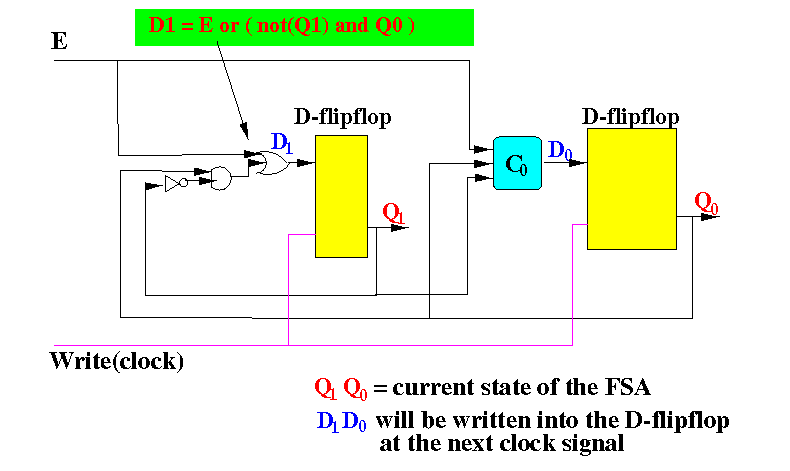
DEMO: /home/cs355001/demo/circuits/seq-circuit1
How to design a
FSM using
digital circuits
This version also probe the inputs of the D-fliplops:
DEMO "how the FSM works": /home/cs355001/demo/circuits/seq-circuit1-demo
Making a FSM control a stop light
We can make the FSM control a stop light with the following combinatorial circuit:
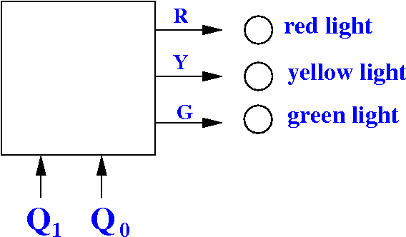
  Logic function computed by this circuit:

     Q1  Q0 | R  Y  G
   ---------+----------
     0   0  | 1  0  0  (Red)
     0   1  | 0  1  0  (Yellow)
     1   0  | 0  0  1  (Green)
     1   1  | 1  1  1  (Flashing)
|
DEMO: /home/cs355001/demo/circuits/seq-circuit1-demo-plus-light
Viewing the stop-light FSM as staged processing
The following diagram shows an another way to draw the FSM circuit of stop-light
Viewing the stop-light FSM as staged processing
In the diagram, you can clearly see a computation stage followed by a memory stage:
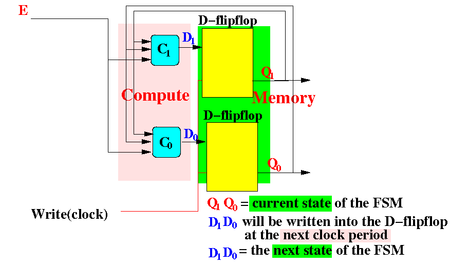
A CPU is also a FSM, but will have more stages and more complex compute/forward circuits