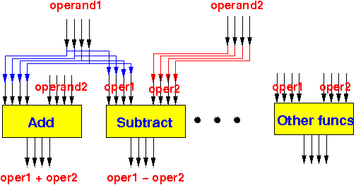
If you would ask a fellow human to compute 3 + 4, he/she would most likely only do "3 + 4", he/she would not compute "3 - 4", "3 * 4", "3 / 4", etc, etc. because you did not ask for it.
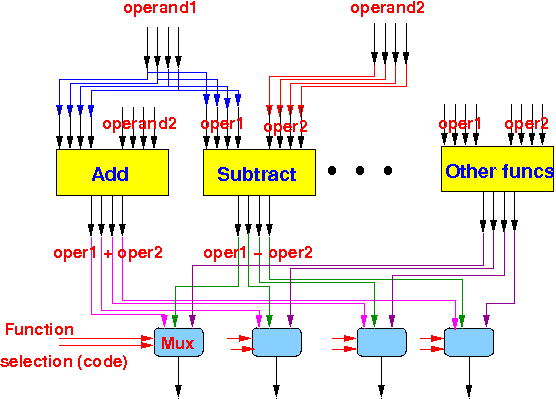
The ability of the ALU to do the different kinds of operations is derived from a many-to-one switch... yep, the multiplexor:
- The ALU performs every possible operation on its inputs and then use multiplexors to pick out the desired result.
We will use these computational cicuits and perform every possible computation that the CPU is capable on the input operands:

|
Then we select the result that we want using a multiplexor:

|
That is in a nut shell how an ALU works....
The function selection code are signals from the Instruction Register.
There are bits in the machine instruction that encodes the operation that the CPU must peform.
These bits are used to select the desired output from all the possible computed outputs !!!
(Yes, it's wasteful. You can add circuitry to shot off some circuits to save energy - happens on low power-version of CPU for laptops)
Our ALU will only have 4 operations: +, NOT, AND and OR....
And the operands (and result) of the ALU are 4 bits long...
To select the desired operation among the 4 different possible operations, we will need 2 "function" bits:
- 00 will mean: operand1 + operand2
- 01 will mean NOT(operand1)
- 10 will mean operand1 AND operand2
- 11 will mean operand1 OR operand2
The following figure shows our ALU and an example operation:

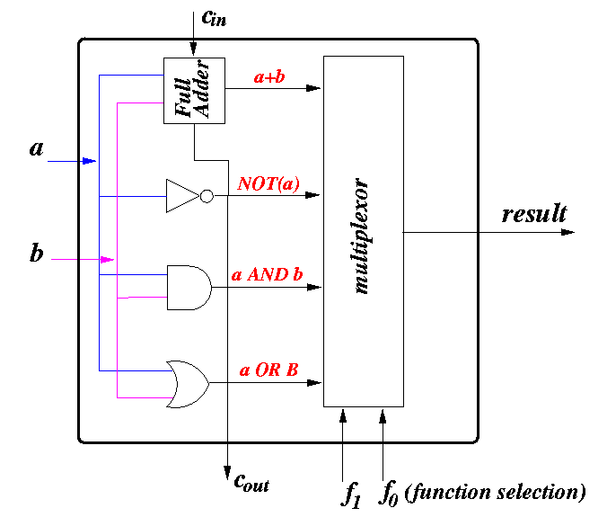
We will first design a 1-bit-ALU circuit that can perform the desired operations on 1 bit operands.
We will than cascade this 1-bit-ALU circuit to obtain an ALU that can perform the desired operations operands of any length.

- The inputs of the circuit are:
- a = operand1
- b = operand2
- cin = carry in (we need that to do addition)
- The outputs of the circuit are:
- result = outcome of the operation
- cout = carry out (we need that to do addition)
- The circuit first computes all the possible outcomes: a+b, NOT(a),
(a AND b), and (a OR b).
- The desired result is then selected using a multiplexor,
the control signal of the multiplexor will be the
operation code in the computer instruction
(stored in the IR - instruction register)
- I have a logic-sim circuit program that illustrates the operation of this 1-bit ALU: click here .

- Note: I did not complete the connections from
a1, a2, b1 and b2
to the inputs of their 1-bit ALU's.
From the figure, from the material on the 4-bit adder
( click here),
and from class notes, it should be clear how they should be
connected.
- Same note on the connection from the 1-bit ALU to the outputs z1 and z2.