Background review and context of the problem
that we are discussing
Previously, we studied a circuit that switch the registers' value (= outputs) to the inputs of the ALU:
Background review and context of the problem
that we are discussing
We also studied a circuit that stores the ALU output into the correct destination register:
Background review and context of the problem
that we are discussing
In this set of slides, we will study how the CPU performs the correct operation specified by the (machine) instruction:
Instruction encoding: how a computer instruction is expressed
Each CPU has its own instruction encoding format.
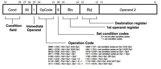
This is the ARM instruction encoding format (each ARM instruction is 32 bits long)
How the CPU uses the different fields
in the ARM instruction
The OpCode field is used to select the desired computed result for output of the ALU:
We will now discuss how this is done
An analogy on how a
CPU operates
A customer arrives at a McDonald restaurant

Represents: a (computation) instruction is being executed by the CPU
An analogy on how a
CPU operates
The restaurant makes every possible menu item

Represents: the CPU compute the result of every possible operation (+, −, ×, /, ...)
An analogy on how a
CPU operates
The customer then presents his/her menu order

Represents: the CPU consults the operation code of the instruction
An analogy on how a
CPU operates
The menu item is selected for the customer according to his/her order

Represents: the CPU will select the desired result according to the operation code
How to construct an
Arithmetic and Logic Unit (ALU)
The ALU operates on the (4 bits) input (binary) numbers a3a2a1a0 and b3b2b1b0 :
This 4 bits ALU design can be easily generalized for 32/64 bits binary numbers
How to construct an
Arithmetic and Logic Unit (ALU)
Add circuits to perform all the ALU operations on the input numebrs:
Here we use an 4 bit adder circuit to compute the sum of the input (binary) numbers
How to construct an
Arithmetic and Logic Unit (ALU)
Add circuits to perform all the ALU operations on the input numebrs:
Here we use an 4 bit subtract circuit to compute the difference of the input numbers
How to construct an
Arithmetic and Logic Unit (ALU)
Add circuits to perform all the ALU operations on the input numebrs:
And so on !!!
How to construct an
Arithmetic and Logic Unit (ALU)
Add multiplexor in order to select the desired result:
The selection is controlled by the op code (field in the instruction stored in the IR !!)
How to construct an
Arithmetic and Logic Unit (ALU)
Connect the op code selection signals to the multiplexors:
All we need to do now is to connect the inputs to the multiplexors...
How to construct an
Arithmetic and Logic Unit (ALU)
Connect the sum output to the 1st input of each multiplexor:
Now: the op code=00 will select the sum (a+b) as result
How to construct an
Arithmetic and Logic Unit (ALU)
Connect the difference output to the 2nd input of each multiplexor:
Now: the op code=01 will select the difference (a−b) as result
How to construct an
Arithmetic and Logic Unit (ALU)
And so on....
The ALU is complete...