The "ripple carry" adder for binary numbers

  • The ripple carry adder circuit is a simple (but less efficient) digital circuit to perform addition of binary number

  • The design of the ripple carry adder is based on binary number additions:

                       CarryIn = 1            
                       <--- 
               1      1      1
            +  1      0      1
          -------------------------


    In order to add a pair of corresponding bits, we only need to know whether the addition of the previous pair produced a carry (=1)

The full adder circuit

  • The full adder digital circuit is a circuit that performs the addition of a corresponding pair of binary digits using a possible carry from the previous stage

  • The design of the full adder circuit is based on the binary number addition:

             CarryOut   CarryIn = 0 or 1            
                 <---  <--- 
               ?      1      ?
            +  ?      0      ?
          -------------------------
                    Sum-Bit
      

    The full adder has these inputs: 2 input bits and a CarryIn bit
    The full adder has these outputs: a Sum bit and a CarryOut bit

Operation of the full adder circuit

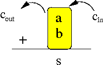
The full adder performs the addition of 2 corresponding bits (a and b) with a carry indication cin:

The sum output s = the sum result of the addition of a, b and cin
The cout output = 1 if the addition produced a carry (and = 0 otherwise)

Designing the full adder circuit
 

The logic table of the full adder circuit is as follows:

        (inputs)      (outputs)
       cin  a   b  |   cout  s
      -------------+----------
       0    0   0  |   0    0
       0    0   1  |   0    1
       0    1   0  |   0    1 
       0    1   1  |   1    0
       1    0   0  |   0    1
       1    0   1  |   1    0
       1    1   0  |   1    0
       1    1   1  |   1    1


We could use the digital circuit design method to construct a (non-optimal) full adder circuit..

The optimal circuit for a full adder
 

Because the full adder is a very important circuit, we have found the optimal solution:

DEMO: /home/cs355001/demo/circuits/1-full-adder.m

The ripple carry adder
 

  • The ripple carry adder is a digital circuit constructed using full adder circuits used to perform addition of binary numbers

  • The ripple carry adder circuit is based on how humans perform binary number additions:

      • Add the corresponding pairs of binary digits from right to left

      • Perform the addition on one pair of binary numbers at a time


I will now show the design of a ripple carry adder to add binary numbers of (upto) 4 bits

The design can be easily generalized for binary numbers of any number of bits

The ripple carry ader for binary numbers of (upto) 4 bits
 

The 4 bits ripple carry adder adds two 4-bits (binary) numbers ( a3a2a1a0 +b b3b2b1b0 ):

The sum of the addition is s3s2s1s0
And cout = 1 if the addition produced a carry output (and cout = 0 otherwise)

The ripple carry ader for binary numbers of (upto) 4 bits
 

We start with putting down the inputs and outputs of the circuit:


The ripple carry ader for binary numbers of (upto) 4 bits
 

Add the last pair of binary digits using one full adder circuit:

The Carry Input = 0 because there were no previous additions !

The ripple carry ader for binary numbers of (upto) 4 bits
 

Then: add the next pair of binary digits using the carry from the previous full adder:


The ripple carry ader for binary numbers of (upto) 4 bits
 

Next: add the next pair of binary digits using the carry from the previous full adder:


The ripple carry ader for binary numbers of (upto) 4 bits
 

Finally: add the last pair of binary digits using the carry from the previous full adder:

DEMO: /home/cs355001/demo/circuits/4-bit-adder.m

Using a user-defined component to construct another user-defined component

  • Do take a look inside /home/cs355001/demo/circuits/4-bit-adder.m:

      Define Full_Adder CarryIn a b | CarryOut Sum;
        Xor aa a b x;
        Xor ab x CarryIn Sum;
        And bb a b y;
        And cb CarryIn x z;
        Or bc-cc y z CarryOut;
      Endef;
      
      Define FourBit_Adder   a3 a2 a1 a0 b3 b2 b1 b0 | CarryOut s3 s2 s1 s0;
         Full_Adder ch ZERO  a0 b0  | c1       s0;
         Full_Adder cf c1    a1 b1  | c2       s1;
         Full_Adder cd c2    a2 b2  | c3       s2;
         Full_Adder cb c3    a3 b3  | CarryOut s3;
      Endef;
      

  • This circuit program shows that you can use a user-defined circuit component to construct another user-defined circuit component !!!

    Syntax rule: you must define a user-defined component before you can use it

The constant inputs ZERO and ONE in EDiSim
 

  • If an input value for a circuit is always constant (= not changing), you can use the keyword ONE as input signal 1

    And use ZERO if the input is always equal to 0

    Example:

      Define FourBit_Adder   a3 a2 a1 a0 b3 b2 b1 b0 | CarryOut s3 s2 s1 s0;
         Full_Adder ch ZERO  a0 b0  | c1       s0;
         Full_Adder cf c1    a1 b1  | c2       s1;
         Full_Adder cd c2    a2 b2  | c3       s2;
         Full_Adder cb c3    a3 b3  | CarryOut s3;
      Endef;