Review of the
CPU
CS255: logical structure of a CPU:
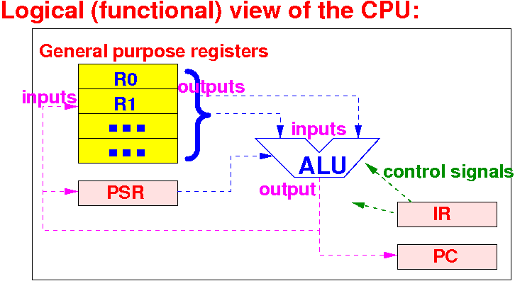
We now start studying how to construct a CPU (to learn how the CPU works)
Review of the
CPU
|
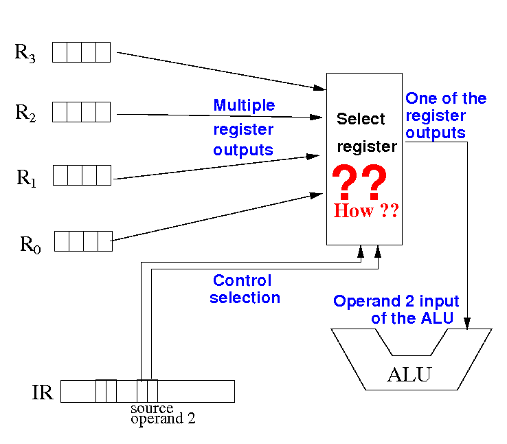
Question: How does the CPU send data from different registers to the ALU ??
The question explained
using the (CS255)
CPU diagram
Problem at hand:
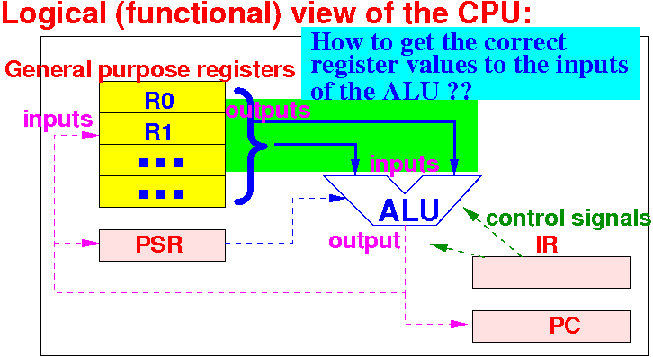
How to get the correct register values (= outputs) to the inputs of the ALU (in order to perform the computation)
The question explained
using the (CS255)
CPU diagram
Example: suppose the instruction is add r10, r3, r9:
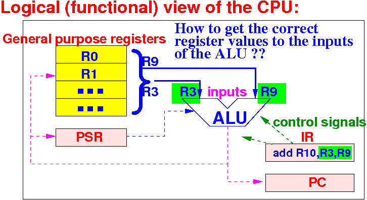
The execution of instruction add R10,R3,R9 needs the values (= outputs) from register 3 and 9.
How can the
CPU send
the correct register values to
the inputs of the
ALU circuit to ???
Review:
Instruction encoding
|
Instruction encoding: how a computer instruction is expressed
Each CPU has its own instruction encoding format.
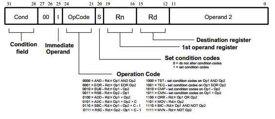
This is the ARM instruction encoding format (each ARM instruction is 32 bits long)
How the CPU uses the different fields
in the ARM instruction
The Rn field is used to select the first operand for input 1 of the ALU:
How the CPU uses the different fields
in the ARM instruction
The Operand2 field is used to select the 2nd operand for input 2 of the ALU:
DEMO: instruction encoding
Compile this assembler program with EGTAPI:
        .text
        .global main
main:
        add r10, r3, r8
        add r10, r4, r7
        add r10, r9, r5
Stop:
CodeEnd:
        nop
|
DEMO: /home/cs355001/demo/instr-encoding/instr-encode.list (see next slide)
DEMO: instruction encoding
Here is the relevant content of instr-encode.list:
3 main: 4 0000 08A083E0 add r10, r3, r8 5 0004 07A084E0 add r10, r4, r7 6 0008 05A089E0 add r10, r9, r5 I marked the instruction codes in red |
Can you see which part of the instruction code represents the 1st register number ???
Can you see which part of the instruction code represents the 2nd register number ???
DEMO: instruction encoding
I highlighted the 1st and 2nd register numbers in the instruction code:
3 main: 4 0000 08A083E0 add r10, r3, r8 5 0004 07A084E0 add r10, r4, r7 6 0008 05A089E0 add r10, r9, r5 Note: bytes are stored in little endian order E.g.: 1st instr code = E083A008 |
Can you see which part of the instruction code represents the 1st register number ???
Can you see which part of the instruction code represents the 2nd register number ???
Problem description:
selecting input registers for an instruction
In order to execute the instruction add r10, r1, r3, the values in registers r1 and r3 must be forwarded to the inputs of the ALU:
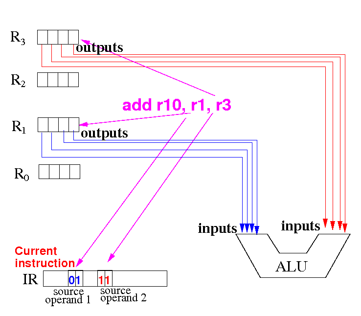
Notice that: the source operand fields in the the current instruction add r10,r1,r3 will contains the codes for r1 (= 01) and r3 (= 11)
Problem description:
selecting input registers for an instruction
On the other hand, in order to execute the instruction add r10, r0, r3, the values in registers r0 and r3 must be forwarded to the inputs of the ALU:
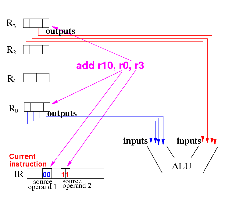
Notice that: the source operand fields in the the current instruction add r10,r0,r3 will contains the codes for r0 (= 00) and r3 (= 11)
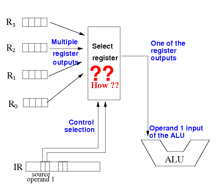
How do the
CPU select the
register operands for
the operation
Summary of solution: the instruction code inside the Instruction register IR will make the selection
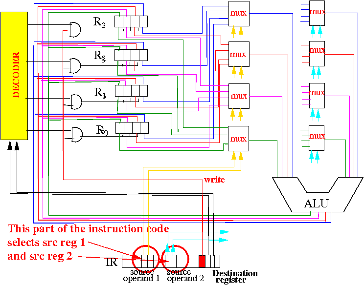
The source register (operand) 1 and source register (operand) 2 sub-fields in the IR sends out control signals to multiplexors to select the operands in the given register number (explained next)
We must solve 2 selection problems
Selection problem 1: how to select the source register 1:
The source register 1 is selected according to the source op 1 field
We must solve 2 selection problems
Selection problem 2: how to select the source register 2:
The source register 2 is selected according to the source op 2 field
Selecting the source register 1 (left ALU input)
I will show you how to select source register 1:
I will use a 4 bits register, the solution can easily be generalized !
Selecting the source register 1 (left ALU input)
Use one 4x1 Mux to select the bit 0 from each register for the bit 0 of the ALU input:
The selection is controlled by the source op 1 value in the instruction
Selecting the source register 1 (left ALU input)
Use a second 4x1 Mux to select the bit 1 from each register for the bit 1 of the ALU input:
The selection is also controlled by the source op 1 value !!!
Selecting the source register 1 (left ALU input)
Use a third 4x1 Mux to select the bit 2 from each register for the bit 2 of the ALU input:
The selection is also controlled by the source op 1 value !!!
Selecting the source register 1 (left ALU input)
Use a fourth 4x1 Mux to select the bit 3 from each register for the bit 3 of the ALU input:
The selection is also controlled by the source op 1 value !!!
How does
selecting the source register 1 work ?
When source operand 1 field = 00, the multiplexors will select all bits from register R0:
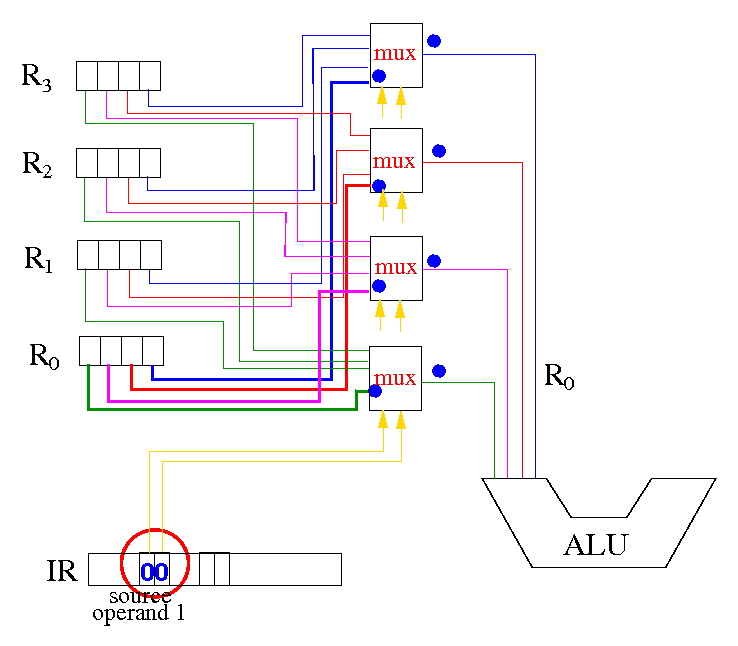
Then source operand 1 = R0 !!!
How does
selecting the source register 1 work ?
When source operand 1 field = 01, the multiplexors will select all bits from register R1:
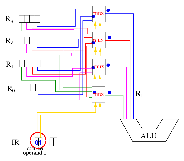
Then source operand 1 = R1 !!! And so on !!!
Selection circuit for source operand 2
Selection circuit for 2nd input operand is the same circuit:
Only difference: selection is controlled by the source op 2 field
DEMO
|