The need to make your own components
|
A concrete example
We have learned how to make a multiplexor circuit previously:
We must to make many connections to construct a multiplexor circuit !!!
A concrete example
Suppose we need more multiplexor circuits in our project:
How can we avoid make all the (similar) connections all over again ?
Define and
instatiating
sser-defined circuit components
Syntax to define a user-defined circuit component:
 Define  CompName  inSigParams  | outSigParams ;
    CircuitComponent1;
    CircuitComponent2;
    ....
    ....
 Endef;
|
Syntax to use a (already defined) user-defined circuit component:
CompName coord inputSigs | outputSigs ; |
Example: defining the
multiplexor
as a user-defined circuit component
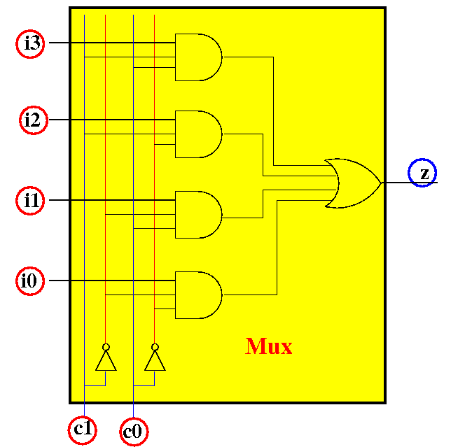
We have previously studied the multiplexor circuit:
The input signals are:
i3, i2, i1, i0 and
c1, c0
The output signal is:
z
Example: defining the
multiplexor
as a user-defined circuit component
(1): specify the component name, input signal names and the output signal name(s):
|
|
The input signals are:
i3, i2, i1, i0 and
c1, c0
The output signal is:
z
Example: defining the
multiplexor
as a user-defined circuit component
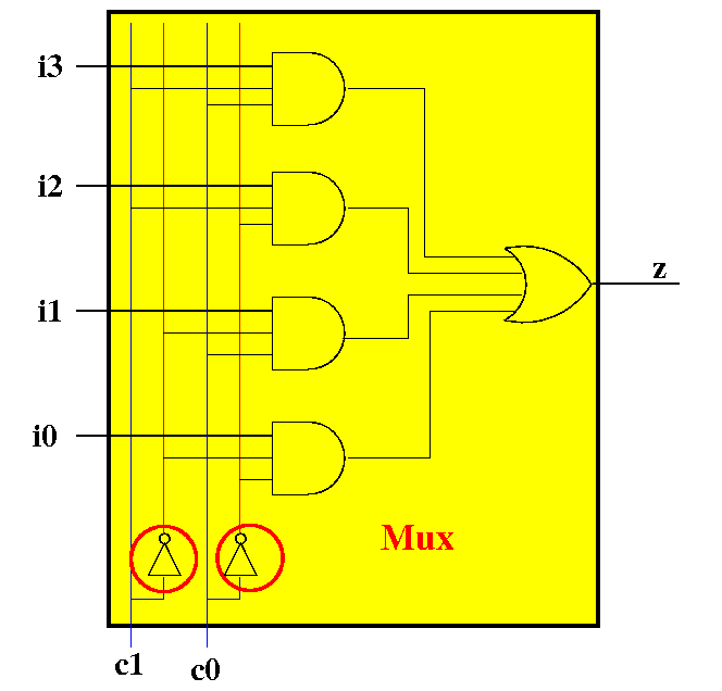
(2): use the input names as inputs signals to compute the output signal(s):
|
|
(2a): connect the
NOT-gates
Example: defining the
multiplexor
as a user-defined circuit component
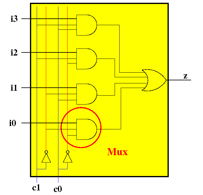
(2): use the input names as inputs signals to compute the output signal(s):
|
|
(2b): connect the
first
AND-gates
Example: defining the
multiplexor
as a user-defined circuit component
(2): use the input names as inputs signals to compute the output signal(s):
|
|
(2c): connect the
other
AND-gates
Example: defining the
multiplexor
as a user-defined circuit component
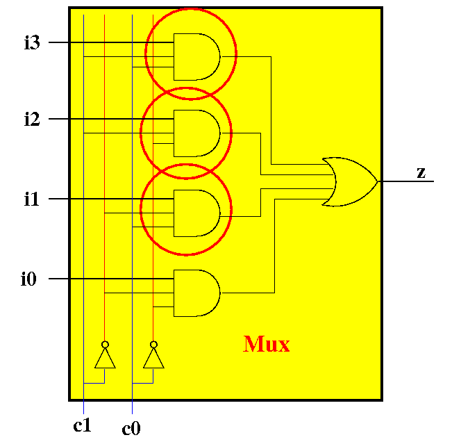
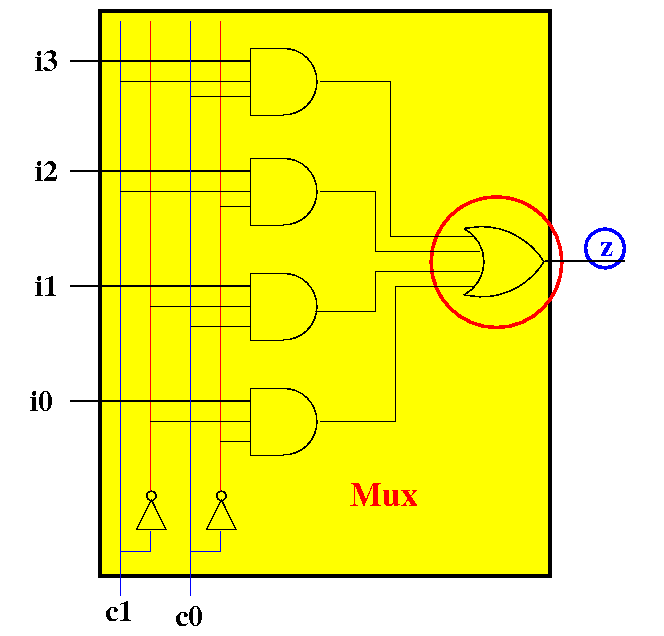
(2): use the input names as inputs signals to compute the output signal(s):
|
|
(2d): connect the
OR-gates and
compute the
output signal z !
DONE !!!
Example:
use a
user-defined circuit component
Example: we can instantiate/create two MyMux components as follows:
MyMux aa x3 x2 x1 x0 c1 c0 | o1; // Mux 1 MyMux aa y3 y2 y1 y0 c1 c0 | o2; // Mux 2 |
Mux1 will
multiplex the inputs
x3 x2 x1 x0
to the output
o1
Mux2 will
multiplex the inputs
y3 y2 y1 y0
to the output
o2
Both multiplexors are controlled by the control signal c1 c0
Example:
use a
user-defined circuit component
Example EDiSim circuit program with a MyMux component:
Define MyMux i3 i2 i1 i0 c1 c0 | z;
  Not    fb   c1 n_c1;
  Not    fb   c0 n_c0;

  And    dc   i0 n_c1 n_c0    o_0;
  And    ec   i1 n_c1     c0    o_1;
  And    bc   i2     c1 n_c0    o_2;
  And    ac   i3     c1     c0    o_3;
  Or     cd   o_3  o_2  o_1 o_0   z;
Endef;

Switch aa sw3 '3' ZERO;
Switch ba sw2 '2' ZERO;
Switch ca sw1 '1' ZERO;
Switch da sw0 '0' ZERO;

Switch gb sw4 '4' ZERO;
Switch gc sw5 '5' ZERO;

MyMux ab-ec sw3 sw2 sw1 sw0 sw5 sw4 | out;

Probe ce  out;
|
DEMO: /home/cs355001/demo/circuits/mux.m
Type control-M to "zoom in" and control-N to "zoom out"
Important mistake
to avoid when
defining a user-defined component
Important note:
|
Why do we need multiple
multiplexors ?
One 4×1 multiplexor allows us to select one 1 bit number among 4 1 bit numbers:
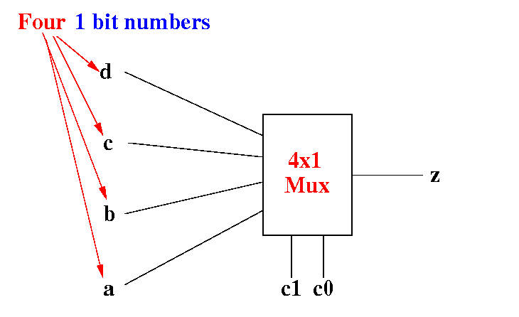
(In general, a 2n×1 multiplexor allows us to choose one 1 bit number among 2n 1 bit numbers)
Why do we need multiple
multiplexors ?
Suppose we want to select one 2 bits number among 4 2 bits numbers
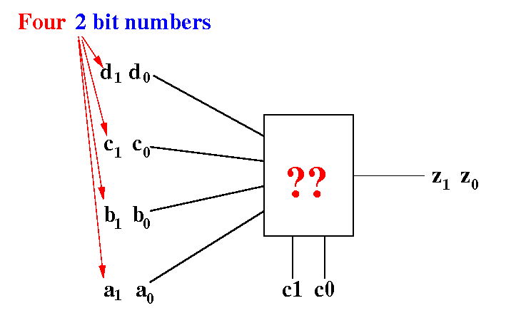
Outputs z1 z0 is equal to one of the inputs d1 d0, c1 c0, b1 b0 or a1 a0 depending on the values c1 c0
Why do we need multiple
multiplexors ?
Solution: we use one 4×1 multiplexor to select the bit 0 of each number:
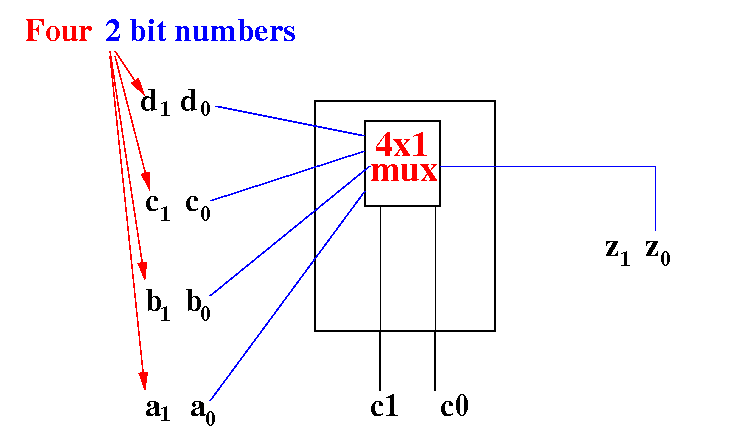
Outputs z0 is equal to one of the inputs d0, c0, b0 or a0 depending on the values c1 c0
Why do we need multiple
multiplexors ?
Solution: we use another 4×1 multiplexor to select the bit 1 of each number:
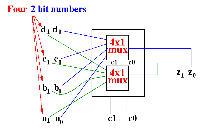
Outputs z1 is equal to one of the inputs d1, c1, b1 or a1 depending on the same values c1 c0
I.e.: the 2 multiplexors work in parallel, each one selecting one bit of the same 2 bits (binary) number !!
DEMO:: /home/cs355001/demo/circuits/parallel-mux