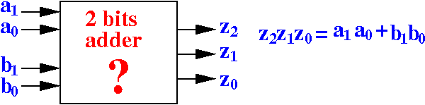
Yet another circuit design problem
Problem description:
|
(Show the behavior: /home/cs355001/demo/circuits/2-bit-adder)
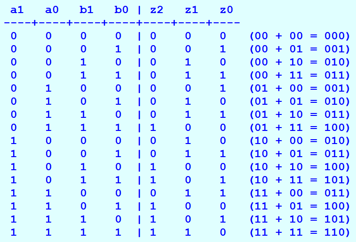
A circuit design algorithm
Step 1: list out every combination of the input values
    a1   a0   b1   b0 | z2   z1   z0
   ----+----+----+----+----+----+----
    0    0    0    0  |
    0    0    0    1  |
    0    0    1    0  |
    0    0    1    1  |
    0    1    0    0  |
    0    1    0    1  |
    0    1    1    0  |
    0    1    1    1  |
    1    0    0    0  |
    1    0    0    1  |
    1    0    1    0  |
    1    0    1    1  |
    1    1    0    0  |
    1    1    0    1  |
    1    1    1    0  |
    1    1    1    1  |
|
A circuit design algorithm
Step 1: list out every combination of the input values
    a1   a0   b1   b0 | z2   z1   z0
   ----+----+----+----+----+----+----
    0    0    0    0  |  0    0    0   (00 + 00 = 000)
    0    0    0    1  |  0    0    1   (00 + 01 = 001)
    0    0    1    0  |
    0    0    1    1  |
    0    1    0    0  |
    0    1    0    1  |
    0    1    1    0  |
    0    1    1    1  |
    1    0    0    0  |
    1    0    0    1  |
    1    0    1    0  |
    1    0    1    1  |  1    0    1   (10 + 11 = 101)
    1    1    0    0  |
    1    1    0    1  |  And so on...
    1    1    1    0  |
    1    1    1    1  |
|
A circuit design algorithm
Step 2: determine the output for each combination of input values
|
Click on table to pull out
Use the logic table to
construct the digital circuit
I will only show the circuit that computes z2:
EDiSim circuit simulation program for the 2 bit addition circuit
Switch ba a0 '0' ZERO; Not ba a0 na0; Switch aa a1 '1' ZERO; Not aa a1 na1; Switch da b1 '2' ZERO; Not da b1 nb1; Switch ea b0 '3' ZERO; Not ea b0 nb0; /* -------- Carry --------------*/ And bb nb1 b0 a1 a0 c1; And bb b1 nb0 a1 na0 c2; And bb b1 nb0 a1 a0 c3; And bb b1 b0 na1 a0 c4; And bb b1 b0 a1 na0 c5; And bb b1 b0 a1 a0 c6; /* -------- sum digit 1 --------------*/ And cb nb1 nb0 a1 na0 s11; And cb nb1 nb0 a1 a0 s12; And cb nb1 b0 na1 a0 s13; And cb nb1 b0 a1 na0 s14; And cb b1 nb0 na1 na0 s15; And cb b1 nb0 na1 a0 s16; And cb b1 b0 na1 na0 s17; And cb b1 b0 a1 a0 s18; /* -------- sum digit 0 --------------*/ And db nb1 nb0 na1 a0 s01; And db nb1 nb0 a1 a0 s02; And db nb1 b0 na1 na0 s03; And db nb1 b0 a1 na0 s04; And db b1 nb0 na1 a0 s05; And db b1 nb0 a1 a0 s06; And db b1 b0 na1 na0 s07; And db b1 b0 a1 na0 s08; Or bc c1 c2 c3 c4 c5 c6 Carry; Or cc s11 s12 s13 s14 s15 s16 s17 s18 s1; Or dc s01 s02 s03 s04 s05 s06 s07 s08 s0; /* -------------- Probes ---------------*/ Probe bd Carry; Probe cd s1; Probe dd s0; |
DEMO: /home/cs355001/demo/circuits/2-bit-adder