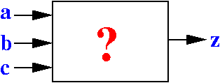
A circuit design problem
Problem description:
|
A circuit design algorithm
Step 1: list out every combination of the input values
    a   b   c | z
   ---+---+---+---
    0   0   0 |
    0   0   1 |
    0   1   0 |
    0   1   1 |
    1   0   0 |
    1   0   1 |
    1   1   0 |
    1   1   1 |
|
A circuit design algorithm
Step 2: determine the output for each combination of input values
    a   b   c | z
   ---+---+---+---
    0   0   0 | 0  (< 2 input values = 1)
    0   0   1 |
    0   1   0 |
    0   1   1 |
    1   0   0 |
    1   0   1 |
    1   1   0 |
    1   1   1 |
|
A circuit design algorithm
Step 2: determine the output for each combination of input values
    a   b   c | z
   ---+---+---+---
    0   0   0 | 0
    0   0   1 | 0  (< 2 input values = 1)
    0   1   0 |
    0   1   1 |
    1   0   0 |
    1   0   1 |
    1   1   0 |
    1   1   1 |
|
A circuit design algorithm
Step 2: determine the output for each combination of input values
    a   b   c | z
   ---+---+---+---
    0   0   0 | 0
    0   0   1 | 0
    0   1   0 | 0  (< 2 input values = 1)
    0   1   1 |
    1   0   0 |
    1   0   1 |
    1   1   0 |
    1   1   1 |
|
A circuit design algorithm
Step 2: determine the output for each combination of input values
    a   b   c | z
   ---+---+---+---
    0   0   0 | 0
    0   0   1 | 0
    0   1   0 | 0
    0   1   1 | 1  (≥ 2 input values = 1)
    1   0   0 |    (And so on)...
    1   0   1 |
    1   1   0 |
    1   1   1 |
|
A circuit design algorithm
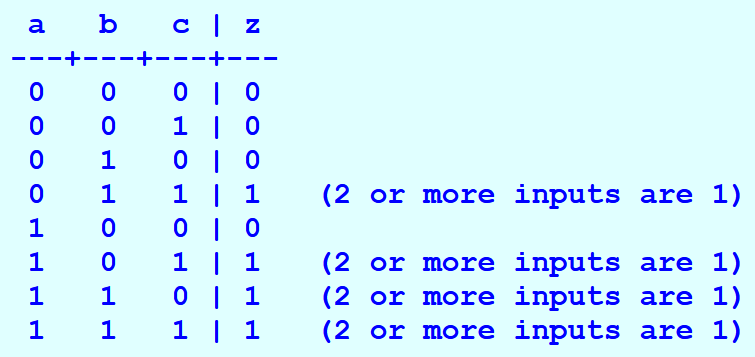
Complete table:
    a   b   c | z
   ---+---+---+---
    0   0   0 | 0
    0   0   1 | 0
    0   1   0 | 0
    0   1   1 | 1
    1   0   0 | 0
    1   0   1 | 1
    1   1   0 | 1
    1   1   1 | 1
|
A circuit design algorithm
End of Step 2: we have determined the output for each combination of input values
|
This table is called a logic table of the design function
Click on table to pull out
Use the logic table to
construct the digital circuit
Step 1: draw the input signals and the output signal(s)

Use the logic table to
construct the digital circuit
Step 2: add the NOT-gates to obtain all possible input combinations:
A combination of inputs is selected by connecting to the appropriate set of signals
Use the logic table to
construct the digital circuit
Step 3: use one AND gate to compute each z=1 output in the logic table
x1 = 1 if and only if a = 0, b = 1, c = 1
Use the logic table to
construct the digital circuit
Step 3: use one AND gate to compute each z=1 output in the logic table
x2 = 1 if and only if a = 1, b = 0, c = 1
Use the logic table to
construct the digital circuit
Step 3: use one AND gate to compute each z=1 output in the logic table
x3 = 1 if and only if a = 1, b = 1, c = 0
Use the logic table to
construct the digital circuit
Step 3: use one AND gate to compute each z=1 output in the logic table
x4 = 1 if and only if a = 1, b = 1, c = 1
Use the logic table to
construct the digital circuit
Step 4: use one OR gate to combine all cases for z=1
z = 1 if and only if for input values that form cases x1, x2, x3 and x4
EDiSim circuit program for the digital circuit
Switch aa A '0' ZERO; Not aa A nA; Switch ba B '1' ZERO; Not ba B nB; Switch ca C '2' ZERO; Not ca C nC; And bb nA B C x1; And bb A nB C x2; And bb A B nC x3; And bb A B C x4; Or bd x1 x2 x3 x4 z; Probe be z; |
DEMO
I will demo this circuit in class:
Circuit file: /home/cs355001/demo/circuits/majority
Post discussion: different circuits, same function
|
The circuit optimization problem
|
Note on CS355
|