Electric components
All electrical circuits (including digital circuits) are made of these basic electric components:
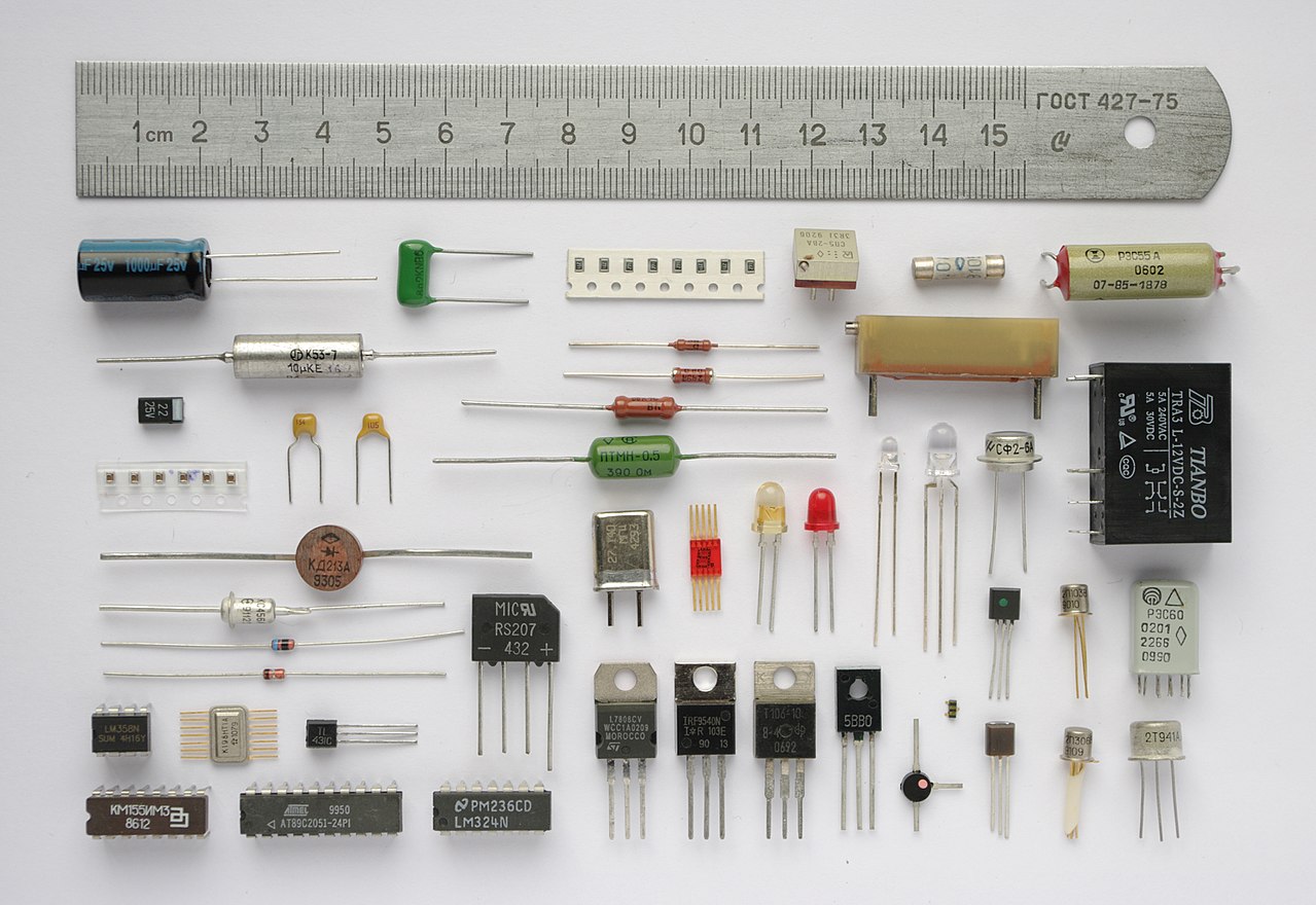
Most commonly used components in digital circuits
Digital circuits are mainly made with these electronic components:
| Resistors | Transistors |
|---|---|
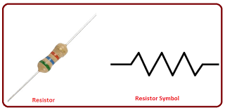
|
|
But: in this course we will not work with basic electronic components
We will be working with basic logical circuits that are built using basic electronic components
Elementary digital circuits
|
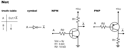
The NOT gate
Symbol and function of the NOT gate:
|
DEMO: cs355sim /home/cs355001/demo/circuits/not
FYEO: How to construct a NOT gate
The AND gate
Symbol and function of the AND gate:
|
DEMO: cs355sim /home/cs355001/demo/circuits/and3
FYEO: How to construct an (2 inputs) AND gate

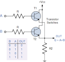
The OR gate
Symbol and function of the OR gate:
|
DEMO: cs355sim /home/cs355001/demo/circuits/or3
FYEO: How to construct an (2 inputs) OR gate
The XOR gate
Symbol and function of the XOR gate:
|
DEMO: cs355sim /home/cs355001/demo/circuits/xor5
The NAND gate
(= Not-AND gate)
Symbol and function of the NAND gate:
|
DEMO: cs355sim /home/cs355001/demo/circuits/nand
The NOR gate
(= Not-OR gate)
Symbol and function of the NOR gate:
|
DEMO: cs355sim /home/cs355001/demo/circuits/nor