- Assumptions:
- In these webpages, I will
use:
- bridge to mean a switch (because the text book and other IEEE 802.11D doucments do so)
- Each bridge has:
- A unique node ID
- Multiple ports
- In these webpages, I will
use:
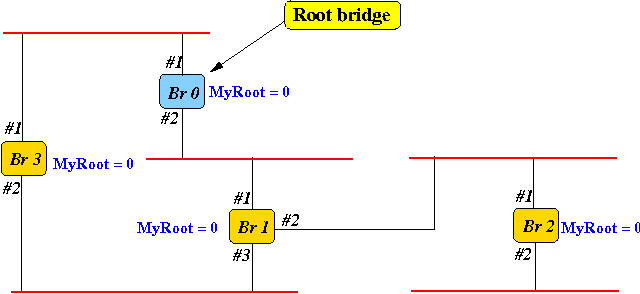
- Root bridge:
- Root bridge in the network = the bridge with the smallest ID
- Example:

- In the figure above:
- Bridge 0 is the root bridge
- Comment:
- Right now, I only want
to
define the
terminologies/concepts
- We will study the algorithm later....
- Right now, I only want
to
define the
terminologies/concepts
- Role of the
root bridge:
- Root bridge = the root of the tree that is constructed by the Spanning Tree algorithm
- Root port:
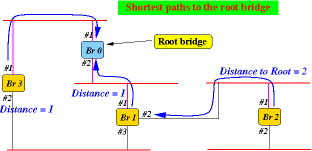
- The root port of a (non-root) bridge = the port that a bridge uses to reach the root bridge in the smallest number of hops.
- Example:
- The blue lines
in the following figure
show the
shortest routes
from a bridge to the
root bridge

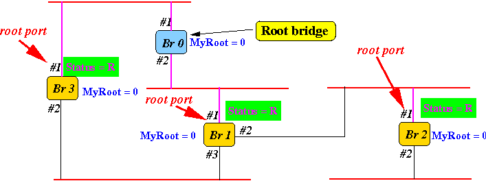
- The root ports
of each bridge are
marked with
"status = R" in
the following figure:

- The blue lines
in the following figure
show the
shortest routes
from a bridge to the
root bridge
- Consider the logical network
spanned by
root bridge
with the root ports of
the non-root bridges:
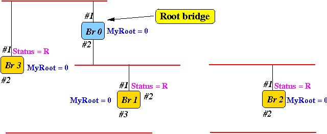
- Original network:

- Logical network
with only the
root bridge and
the root ports:

- Original network:
- Observations:
- The logical network
is loop-free
(which is what we want)...
- However,
the network so far
does not
connect to
all LAN segments
- We still have to fix this !
- The logical network
is loop-free
(which is what we want)...
- Subsequent discussion:
- We need to
add
more ports
to connect all the LANs
in the network
- These additinal ports are called designated ports
- We must be careful
not
to
create a
cycle
while adding ports !!!
- The remaining ports (= not added) are called blocked ports
- We need to
add
more ports
to connect all the LANs
in the network