The Omega Multistage Interconection Network
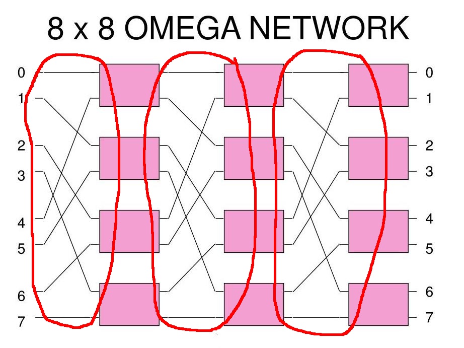
The 8×8 Omega Multistage Interconnection Network has the following structure:
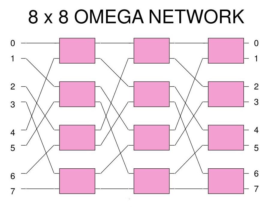
Each rectangle is a 2×2 Banyan switch
How to make
the connections in a
Omega
multistage interconnection network
The output xyz (3 bits) is connected to the input yzx (left rotated):
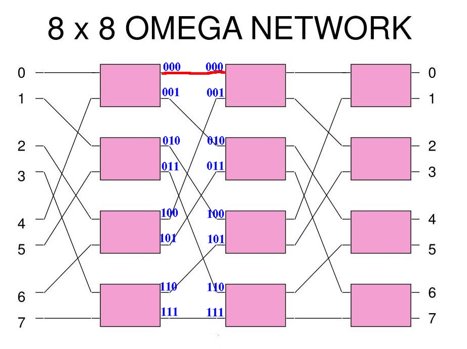
Example 1: output 000 is connected to input 000
How to make
the connections in a
Omega
multistage interconnection network
The output xyz (3 bits) is connected to the input yzx (left rotated):
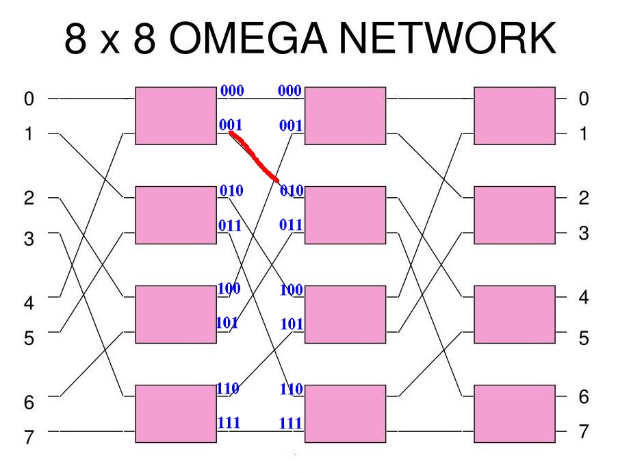
Example 2: output 001 is connected to input 010
How to make
the connections in a
Omega
multistage interconnection network
The output xyz (3 bits) is connected to the input yzx (left rotated):
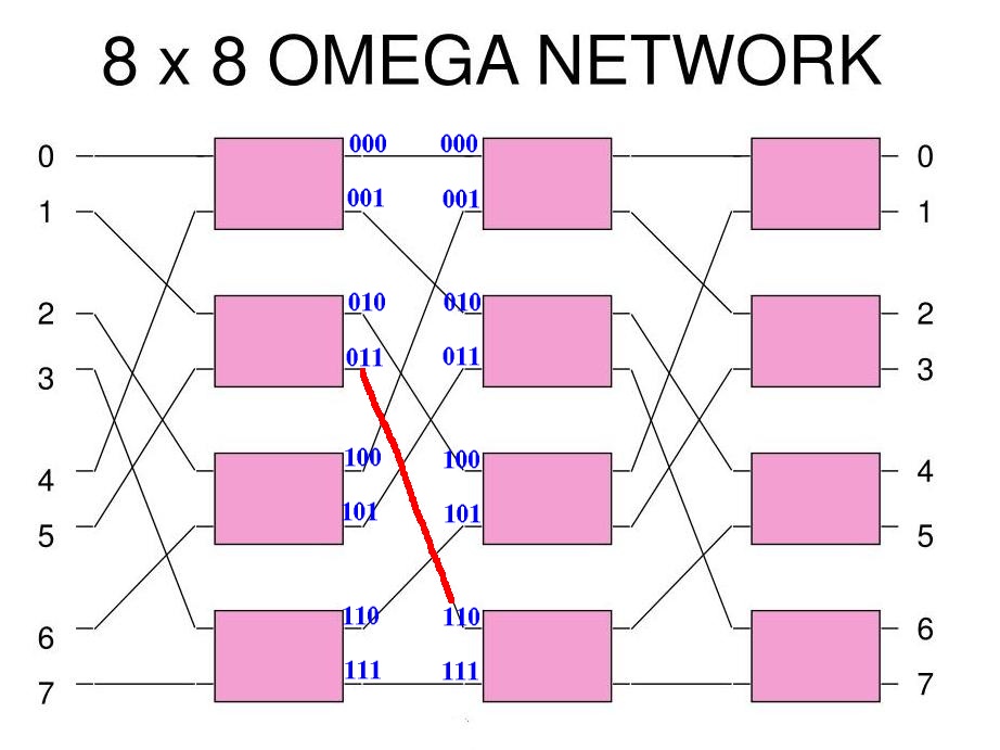
Example 3: output 011 is connected to input 110 --- and so on...
How to make
the connections in a
Omega
multistage interconnection network
The connection pattern is made in all 3 stages of the Omega network:

(We call this pattern a "perfect shuffle")
The Omega network is
also a
self-routing network
Example: CPU 1 wants to access memory module 4 (binary 100):

The connection request will first arrive in the 2nd Banyan switch in layer 1...
The Omega network is
also a
self-routing network
The request 100 will set up the following connection in the Banyan switch:

And the remainder (00) is forwarded to the next switch...
The Omega network is
also a
self-routing network
The request 00 will set up the following connection in the Banyan switch:

And the remainder (0) is forwarded to the next switch...
The Omega network is
also a
self-routing network
The request 0 will set up the following connection in the Banyan switch:
And the path is set up !!!
Why/how does
the Omega network work
The Omega network sorts the requests as follows:
The principle is the same as the Delta switch !
Advantage of
the Omega network
The interconnection pattern of each stage is the same:
Manifacturing
the same connection pattern is
very easy
(Chips are
manufactured using
a process called
Photolithography)