|
Start of cycle 1: IF stage is fetching the cmp instruction:
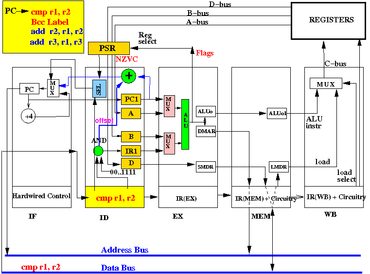
End of cycle 1: cmp instruction is fetched in IR(ID)
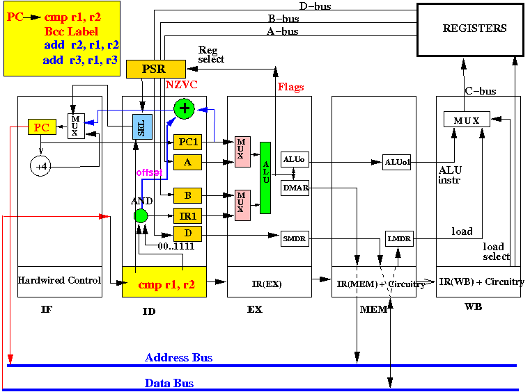
Start of cycle 2: ID stage fetch (all) operands for cmp, IF stage fetch bcc label:
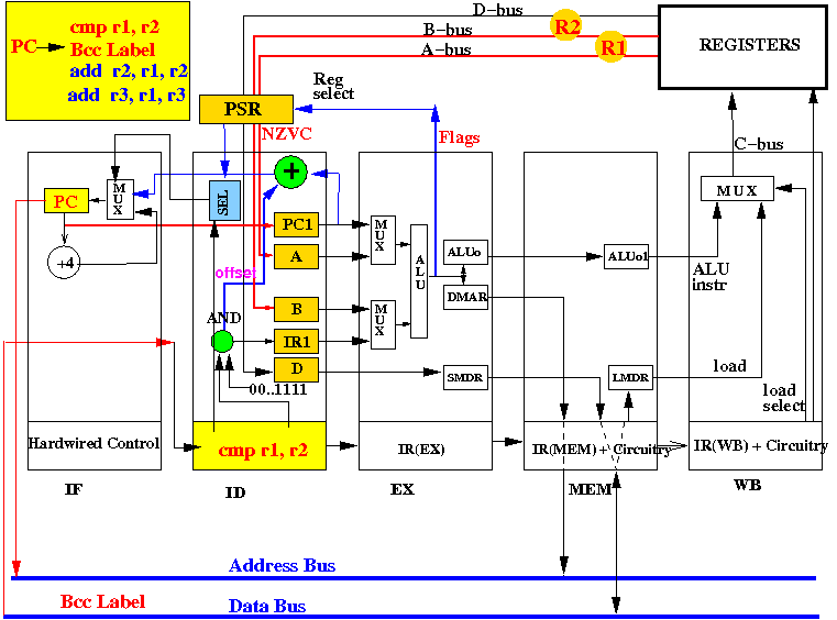
End of cycle 2: fetch (all) operands for cmp fetched, fetch bcc label fetched:
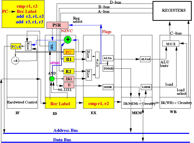
Can we execute the Bcc instr correctly ? (I.e.: can we select the correct new address for the PC?)
Start 2: EX: compare R1.R2, ID: exec bcc , IF: fetch add r2,r1,r2:
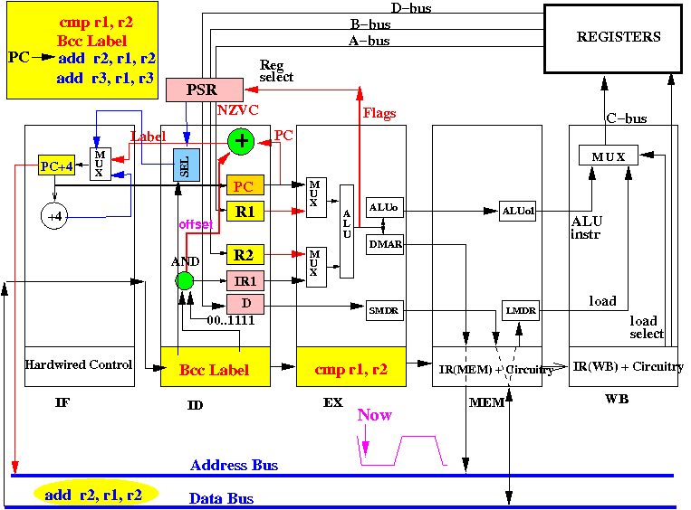
Note: the ALU computes R1−R2 and also computes the values of the N,Z,V,C flags !
Middle of cycle 3: EX: updates the N,Z,V,C flags in the PSR:
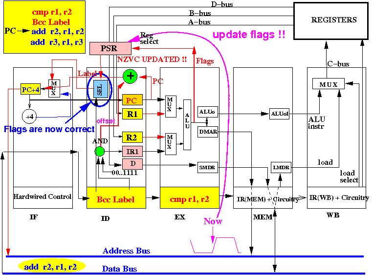
Note: the branch selection circuit can obtain the correct N,Z,V,C flag values !
End of cycle 3: PC is correctly updated to address Label , add r2,r1,r2 is fetched in IR(ID)
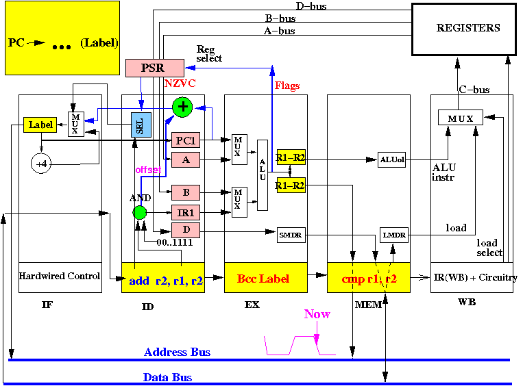
The CPU can correctly execute a conditional branch instruction (with one-instruction branch delay)
The is one circuitry that remains to be discussed:
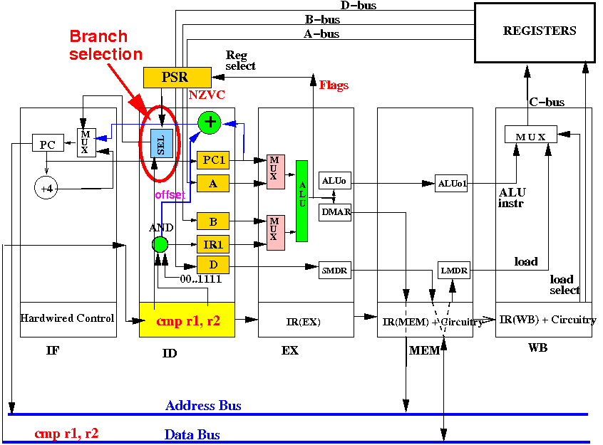
How does the branch selection circuitry work ?
Without going into details of the flag setting (will require me too explain too many details), the following are the flag settings for the branch conditions used in assembler programming taught in CS255:
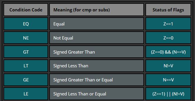
E.g.: the equal condition
is true when
the Z flag = 1
the not equal condition
is true when
the Z flag = 0 - etc
Why x < y is represented by condition flags N != V ?
|
Recall how the branch conditions are encoded in the instruction code (by Aaron):
            Branch
            condition  <-------------- branch offset  ----------->
  +---+---+---+---+---+---+---+---+---+---+---+---+---+---+---+---+
  | 1 | 1 | B | B | B |   |   |   |   |   |   |   |   |   |   |   |
  +---+---+---+---+---+---+---+---+---+---+---+---+---+---+---+---+

    B B B        Branch condition
   ---------------------------------------------------------------
    0 0 0        Branch always
    0 0 1        BEQ
    0 1 0        BNE
    0 1 1        BLT
    1 0 0        BLE
    1 0 1        BGT
    1 1 0        BGE
    1 1 1        not used
|
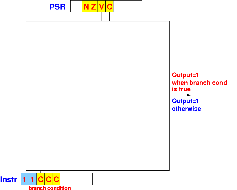
The branch selection circuitry will output 1 when the branch condition is true and 0 otherwise:
We use a decoder to determine the branch condition:
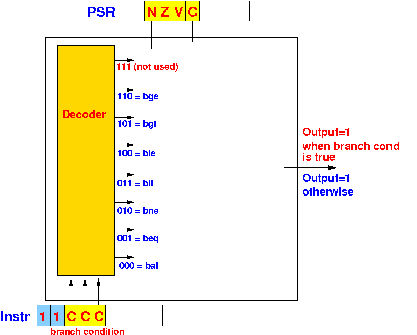
The conditional branch code determines which decoder output = 1
When the decoder detects a branch always instruction, the branch selection = 1:
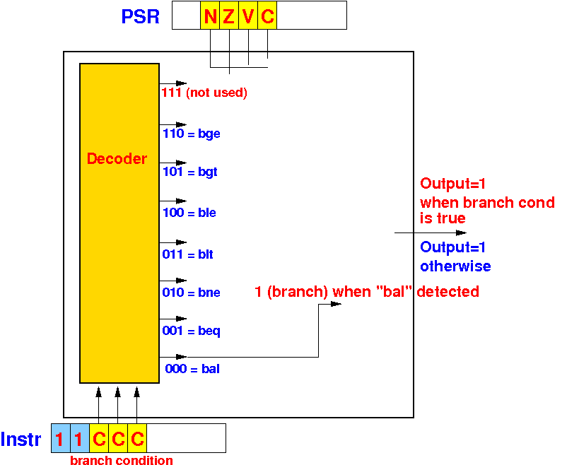
The conditional branch code 000 will cause the branch delection circuit to output 1
For the beq condition (condition code 001) to be true, the Z flag must be equal to 1:
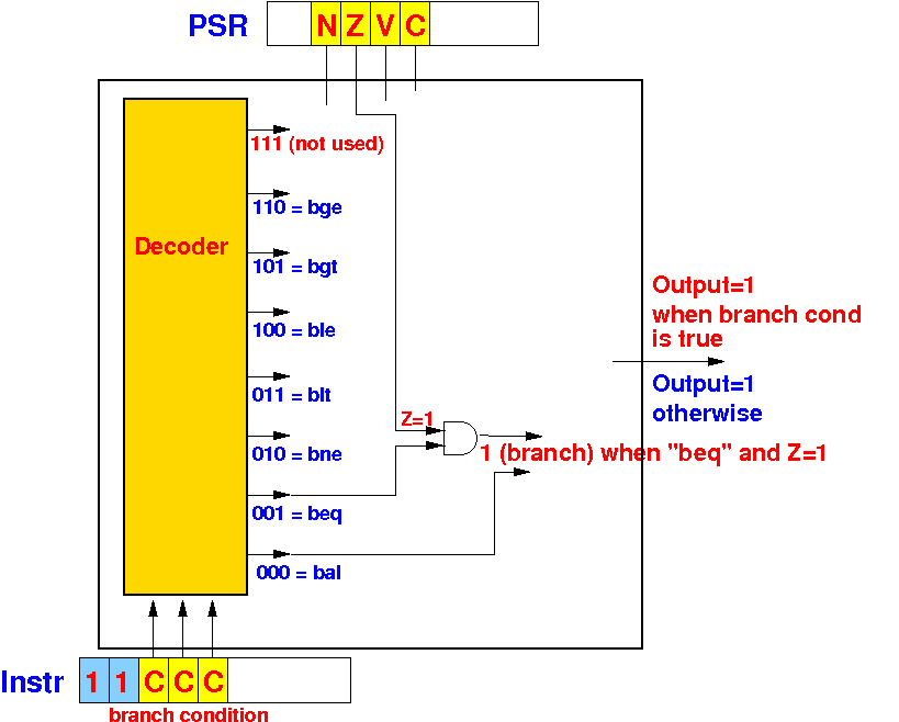
For the bne condition (condition code 010) to be true, the Z flag must be equal to 0:
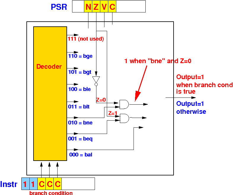
For the blt condition (condition code 011) to be true, the N flag must not equal to the V flag:
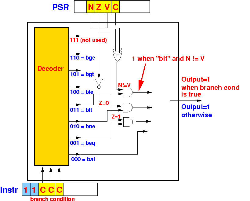
And so on:
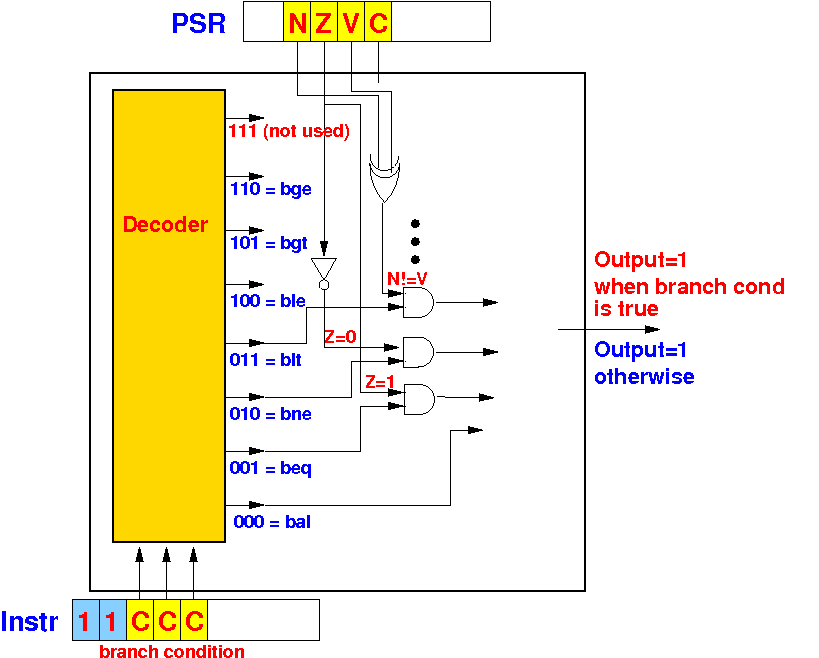
The branch selection must output 1 whenever the flag value fulfills the branch condition !!
We must combine the individual branch cases using an OR-gate:
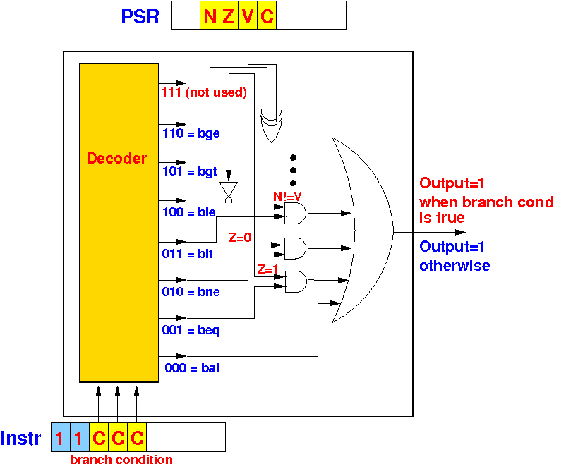
The resulting circuit is the branch selection circuit to determine if the condition for a branch is met !
|
|