Start 4: LD: fetch new R1, EX: computes R1+R4, ID: fetch R1, R5, IF: stalls
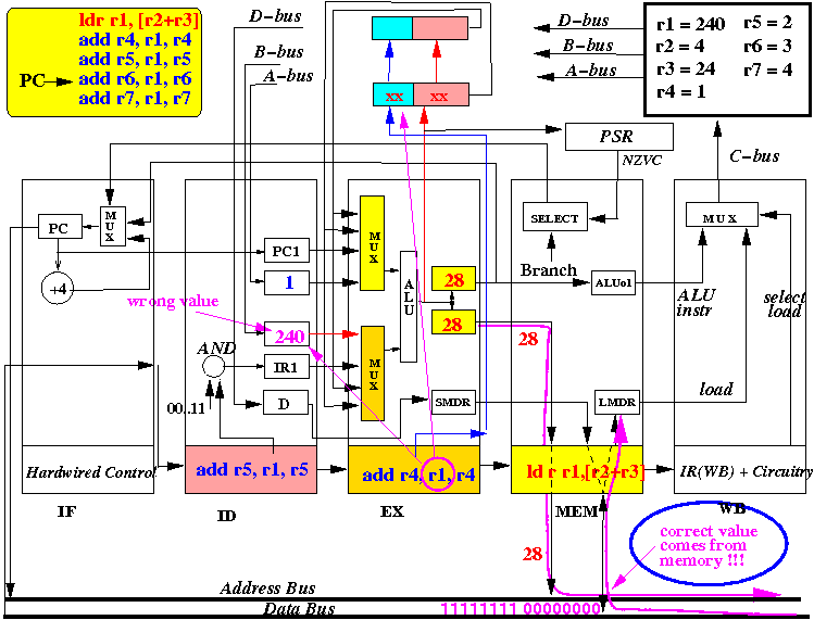
Note: we cannot forward the new R1 value because it has not been fetched yet !!
The first moment that the pipelined CPU uses source operands of an instruction:
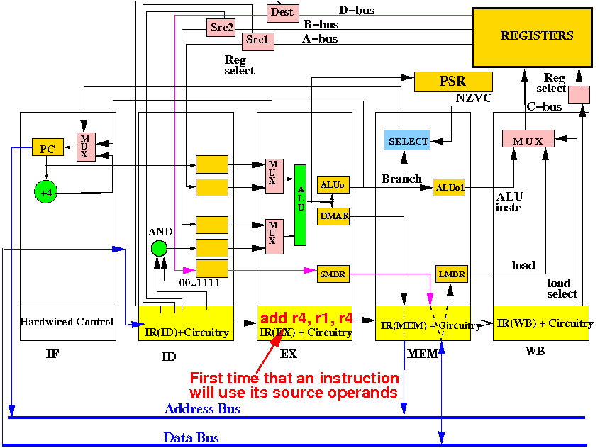
Therefore: the correct operands must be available when an instruction is inside the EX stage !!!
When instruction add r4,r1,r4 is in the EX stage, the new value of R1 is not in the CPU:

Conclussion: the pipelined CPU cannot execute add r4,r1,r4 correctly at this moment !!!
We execute the add r4,r1,r4 instruction at a later time:
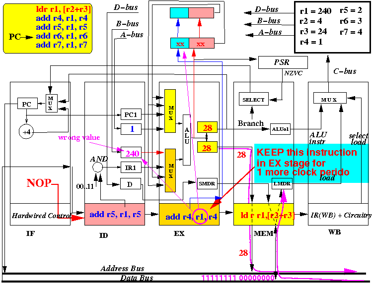
How: block/filter the clock signal (to all memory elements) in EX stage and all prior stages
How to delay the execution in the EX stage explained with diagrams:
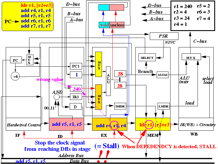
When do we delay: a ldr instruction in MEM stage updates a register used by instr in EX stage
A load instruction data hazard exists when all these 3 conditions hold:
|
The stall logic in pseudo code:
 if ( MEM stage contains a  LDR  instruction        &&
      EX  stage contains an ALU/LDR/STR instruction &&
      (    Destination reg# of MEM stage
             == src1 reg# of EX stage
        || Destination reg# of MEM stage
            == src2 reg# of EX stage )   )
 {
    STALL EX stage, ID stage and IF stage
 }
|
The stall logic constructed in circuit:
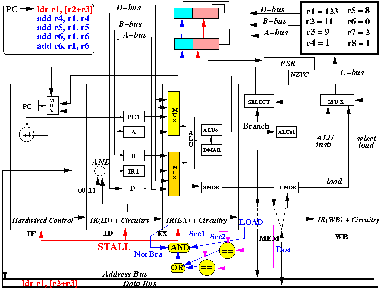
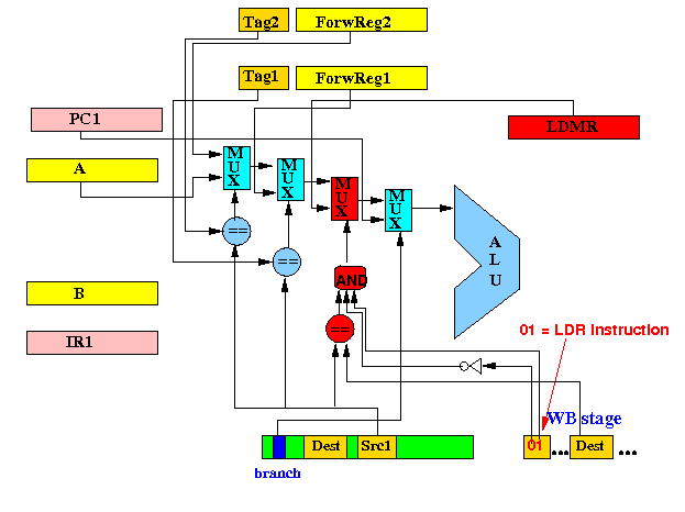
Note: to check for a ldr instruction, we check whether the first 2 bits in instr = 01 !
We delay the execution of add r4,r1,r4 in the EX stage:

Note: the MEM stage and WB stage will continue to operate !!!
After 1 more clock period: ldr instr has fetched the new value for R1
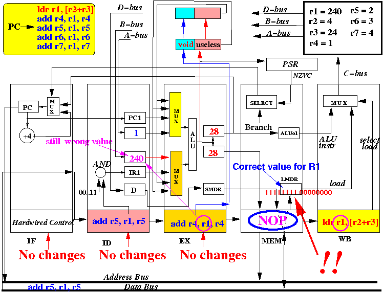
The
new value of
R1 is
now inside the
LMDR reg in the
CPU !!!
However,
the EX stage has
no path way to
obtain the
new value !!!
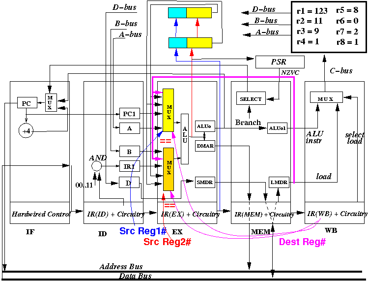
We use the data forwarding technique to allow the EX stage to obtain the new value:
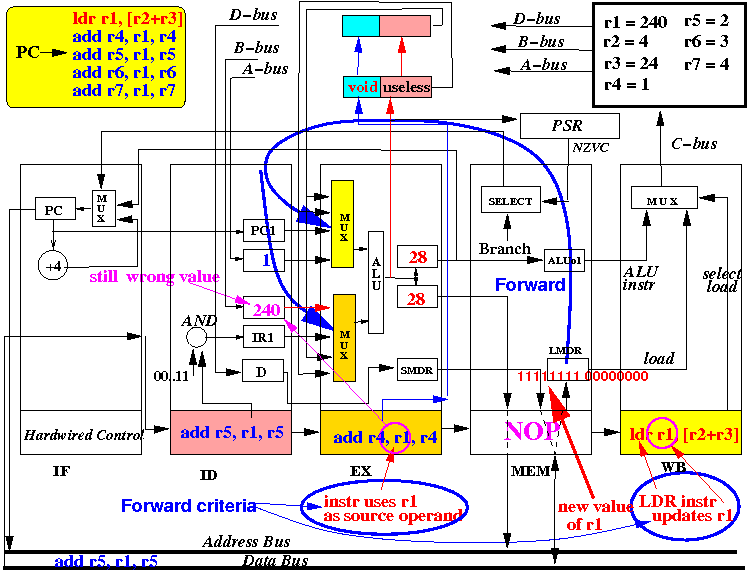
We must determine when the MUXes must use the LMDR value as source operand !!!
(1) add pathway to bring data to the input of the operand selection MUX:
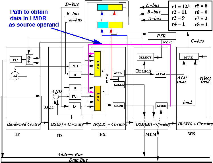
Next: add (= provide) selection logic in the operand selection MUX
(2) make the MUX select LMDR when (1) ldr in WB and (2) EX uses dest reg in WB
I will present the modified operand selection logic of the MUXes next
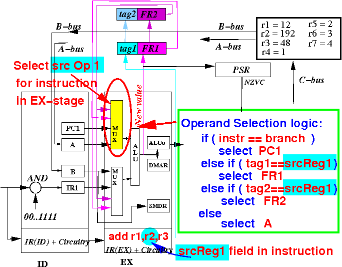
Review: the operand selection logic for source operand 1 with data forwarding was
We still need to add more logic to select LMDR
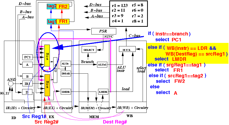
The augmented operand selection logic for source operand 1 with LMDR data forwarding is:
I will show you the circuitry (it's similar to what we have studied before)
The operand selection logic for source operand 2 must also be augmented.... (next slide)
The augmented operand selection logic for source operand 2 with LMDR data forwarding is:
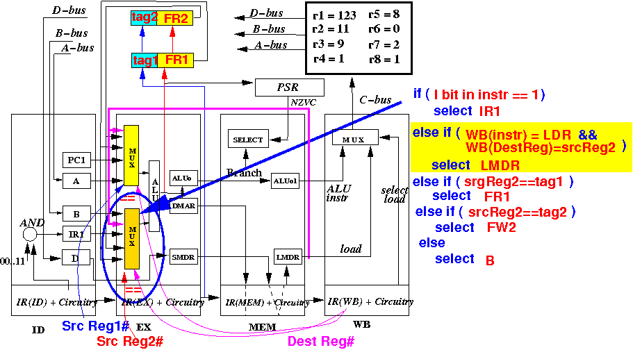
The operand selection circuit for src op 2 is similar to the one used for src op 1 (no diagram)
(1) Add circuitry to detect data dependency and stall IF,ID,EX stages
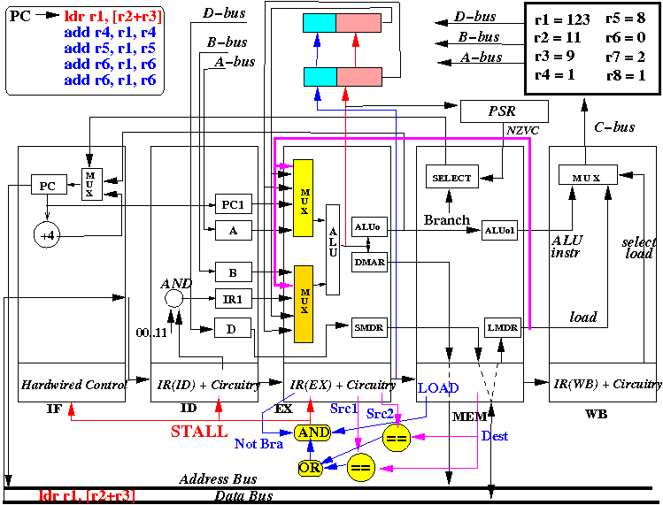
(2) Add data forwarding circuitry to select LMDR as source operand used by the EX stage
How the augmented pipelined CPU solves the data hazard:
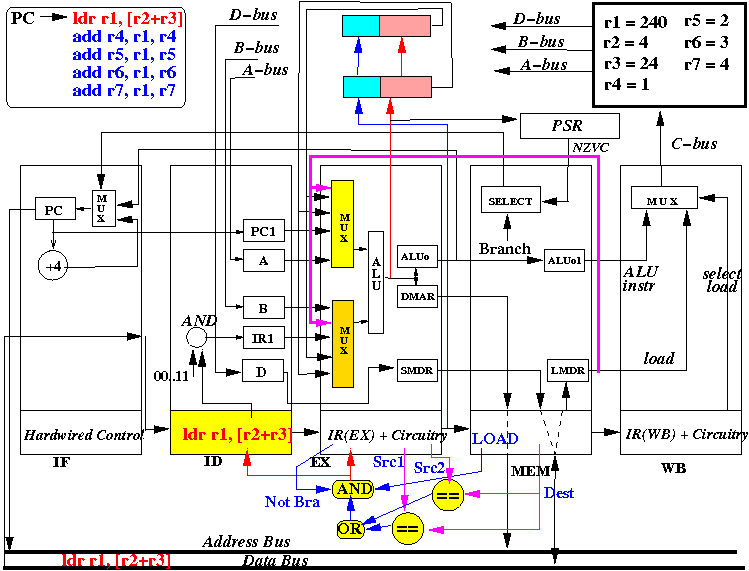
This is the initial state: the ldr instruction has been fetched
Start 2: ID stage fetch operands R2, R3, IF stage fetch add r4,r1,r4,
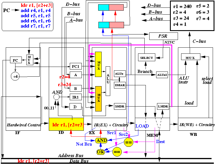
End 2: R2,R3 fetched, add r4,r1,r4 fetched
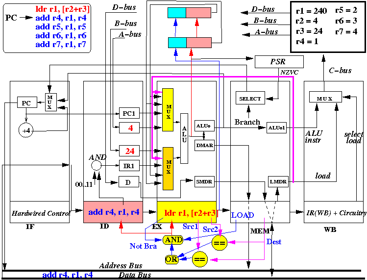
Start 3: EX stage computes R2+R3, ID stage fetch R1, R4, IF stage fetch add r5,r1,r5,
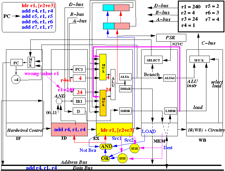
Notice: the new value of R1 must be read from memory (is not computed like add r1,r2,r3) !!
End 3: Address R2+R3 computed, R1,R4 fetched, add r5,r1,r5 fetched
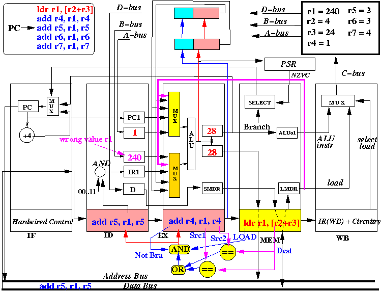
Note: the R1 value in incorrect and the new value is not yet read from memory !!!
Start 4: LD: fetch new R1, detects dependency: stall IF,ID and EX stages
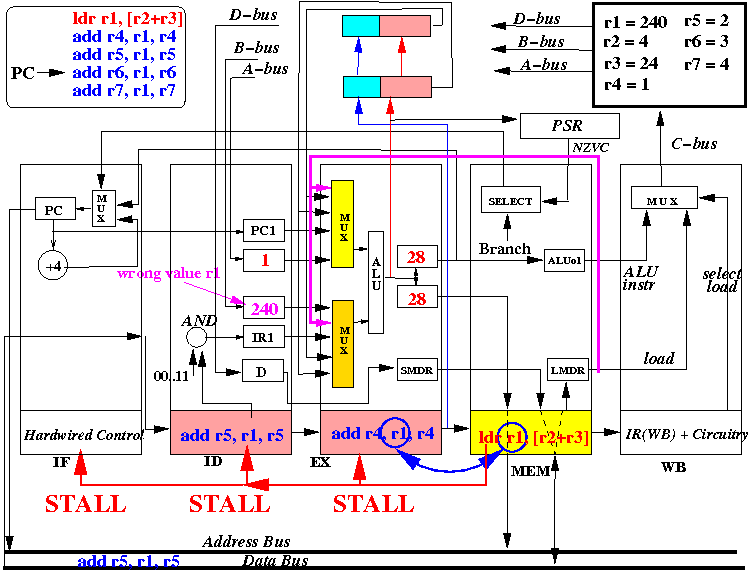
The MEM stage (and the EX stage) continues with their (normal) operation !!!
Start 4: LD: sends out address R2+R3 and read memory
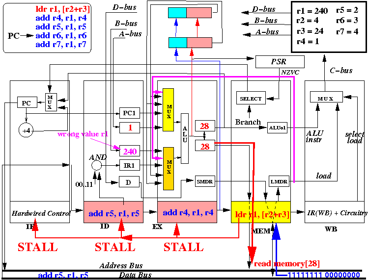
The new value (= 111111111000000000) of R1 will be stored in LMDR
End 4: new R1 value is fetched (in LMDR) - add r4,r1,r4 remainds in the EX stage !!
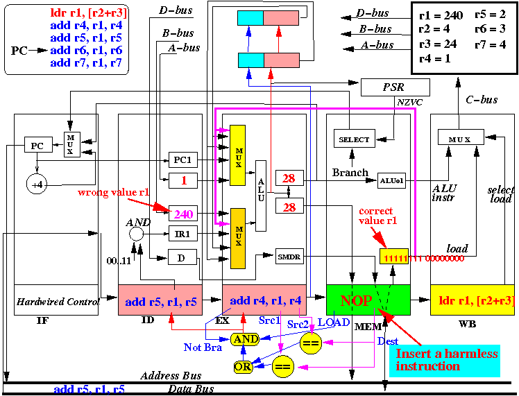
Note: a harmless instruction (NOP - no op) must be inserted into the MEM stage
Start 5: WB: update R1, MEM: No op, EX: compute with LMDR !! ID: fetch R1 !!
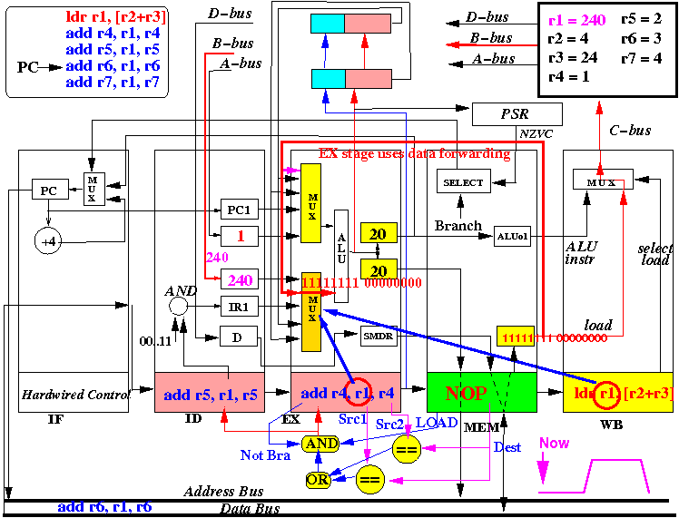
Recall that the general purpose registers are updated in middle of clock period !!
Middle 4: WB: updates register R1 = 1111111100000000 , EX: uses LDMR for R1
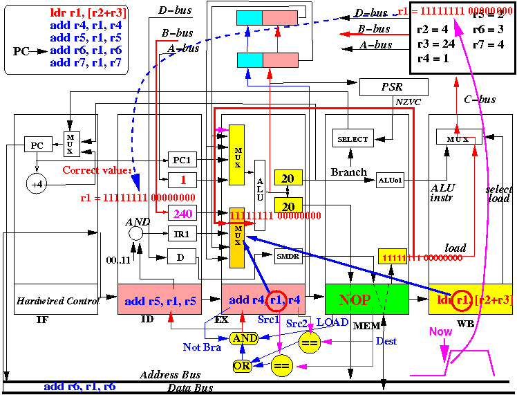
The new value (= 111111111000000000) of R1 is sent to the input of the A reg in the ID stage!
End 5: add r4,r1,r4 correct using LDMR, add r5,r1,r5 fetched the new value from R1
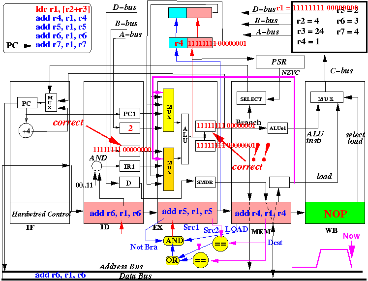
Therefore: both instructions add r4,r1,r4 and add r5,r1,r5 execute correctly !!!
|