Clock cycle 1: The IF stage fetches the instruction into the IR(ID) register
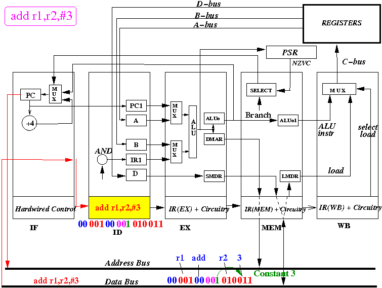
I have include the instruction code in binary
Start of clock cycle 2: the ID stage fetch all possible source operands
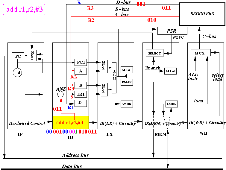
End of clock cycle 2: all source operands are fetched - but only R2 and 3 will be used
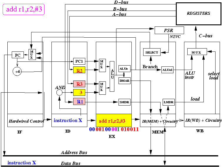
Notice: the instruction is moved into the IR(EX) register
Start of clock cycle 3: the EX stage operates on the correct source operands
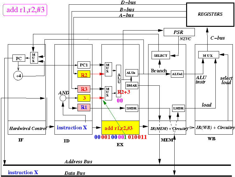
The immediate bit (green bit) = 1 will select the constant 3 for the 2nd source operand.
End of clock cycle 3: the result is stored in ALU Output and the Data Mem Addr registers
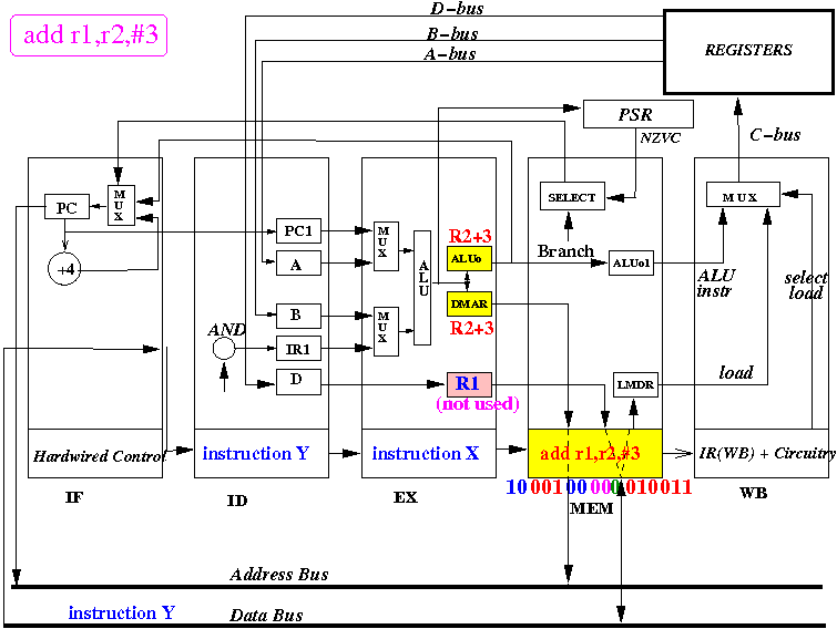
Notice: the instruction is moved into the IR(MEM) register
Start of clock cycle 4: the MEM stage does not perform operation for add r1,r2,#3
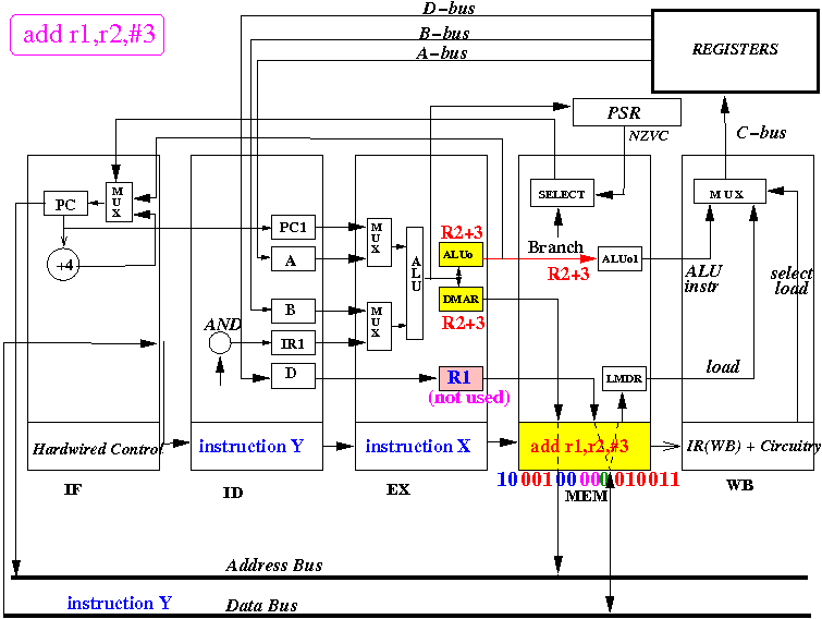
But: we must forward the result(s) further down the pipeline !!
End of clock cycle 4: the result (R2+3) is stored in the ALU Output1 register
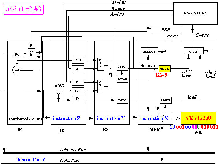
Notice: the instruction is moved into the IR(WB) register
Start of clock cycle 5: the WB stage selects ALU Output 1 as input and update the register R1
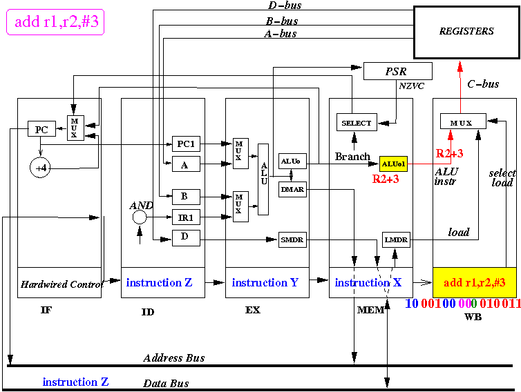
End of clock cycle 5: the result (R2+3) is stored in the register R1
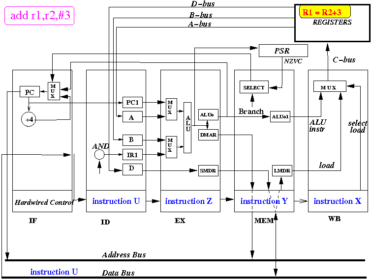
Notice: the instruction has been into the discarded !! (no longer needed !!!)
|