|
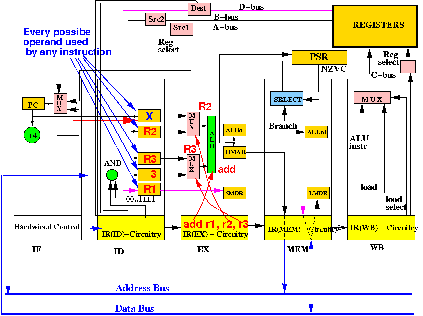
The basic pipelined CPU:

There are 5 stages of processing in the basic pipelined CPU:

Each stage performs a specific task !!
There are 4 Instruction Registers in the CPU - each one controlling a different function/part:

The IF stage does not need an IR because it performs one specific task: fetch next instruction
The (general and special purpose) registers are dark yellow in color:

All (general and special purpose)) registers are updated by a common clock signal (omitted)
PC contains the address of the next instruction:

The CPU sends PC on the address bus to fetch the next instruction
The registers in the ID stage stores the operands for every possible instruction:

The source operands will be used by the EX stage as source operand of the instruction
The ALUOutput and the Data Mem Addr registers store the result of the ALU operation:

The destReg is forwarded so the CPU can execute a str instruction !!
The ALUOutput1 is a buffer to forward the ALU result to the WB stage

The Load Mem Data Reg contains the data fecthed from memory in a ldr instruction
There are multiplexors and decoders are pink. They are used to select the correct inputs:

I omitted some of the control signal inputs to keep the diagram readable...
Computational circuits are green in color:

I omitted the control signals to the ALU to keep the diagram readable
This blue colored SELECT circuit computes the branch decision (0=no branch and 1=branch):

If SELECT outputs 1, PC is updated with the Branch Address. Otherwise: PC = PC+4
At the start of a clock cycle, the IF stage sends out the PC as address and read the memory:

In response, the memory sends back the next instruction on the data bus
At the end of a clock cycle, the next instruction is stored in the IR of the ID stage:

The PC is updated to PC+4 (no branch) or Branch Address. The new address is used to fetch the next instruction
Start of cycle: the IR(ID) sends out src1, src2, dest selection signals to fetch the registers

The ID stage will also fetch the PC (for branching instructions) and the constant operand (e.g.: add r1,r2,#3 inside the instruction in IR(ID).
End of cycle: the ID stage has fetched every possible source operand into its registers

Note: The EX stage can now execute any instruction - because it has all the operands !!
Start of cycle: the EX stage sends out signals to select source operands and ALU operation:

The EX stage can execute the instruction because it has every possible operand !!
End of cycle: the EX stage has saved the result of the operation into its special purpose registers

The EX stage has also forwarded the destReg source operand (to execute a str instruction)
The MEM stage is used to execute a ldr, str or bra instruction.

We will use another sets of slides to show how these instruction execution in detail
For an ALU instruction (e.g.: add r1,r2,r3), the MEM stage just forwards the results:

Start of cycle: the WB stage sends out signals to select destination register and store direction:

Only the ldr instructon will cause the MUX to select the LMDR input !
End of cycle: the EX stage will saved the result of the operation into the destination register

The execution of an instruction is now complete
|