Have you ever wonder how multiple programs seems to be running at the same time:
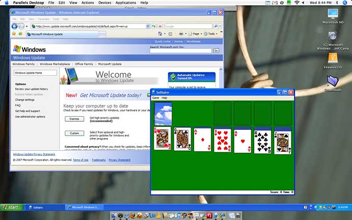
Not so long ago (until 1995), Windows ("DOS") computers could only run 1 program at a time !!
|
|
In this set of slides, I will explained how such a multi-tasking operating system works.
A timesliced (multitasking) operating system is constructed using a timer device:
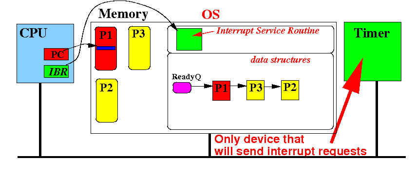
Again, for simplicity, I assume there is only 1 device that can request interrupts
Assume that the process P1 is currently running on the CPU:
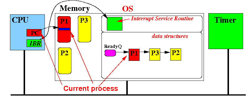
In time slicing, each process will take turn running on the CPU !!!
The timer device periodically sends an interrupt request to the CPU --- say once every 10 msec:
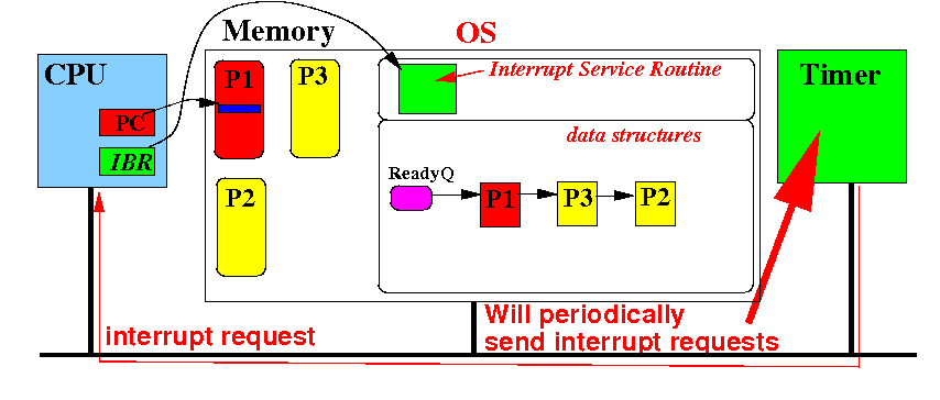
Recall: an interrupt request will cause the CPU to make a "forced" subroutine call !!!
The Interrupt Service Routine for the timer interrupt signal is as follows:
 (1) Acknowledge the interrupt

 (2) Save the context in the CPU into
     the PCB at the head of the Ready Queue

 // Main task performed by the interrupt handler
 (3) Remove the PCB at the head of the Ready Queue
     and insert it at the tail of the Ready Queue
     ("Rotate" the Ready Queue)

 (4) Restore the context using the PCB at the
     head of the Ready Queue

 (5) Return (mov pc, lr)
|
Effect: current process is paused and the next process in the Ready Queue is run on the CPU
I will explain the effect in more details using a number of diagrams next...
Initial situation: the timer device raised (= sent) an interrupt request

The interrupt request will cause the CPU to call the Interrupt Service Routine (at the address given in IBR)
The code of the Interrupt Service Routine was given in the last slide....
The subroutine call will (1) save PC into the LR register and (2) branch the routine @IBR:
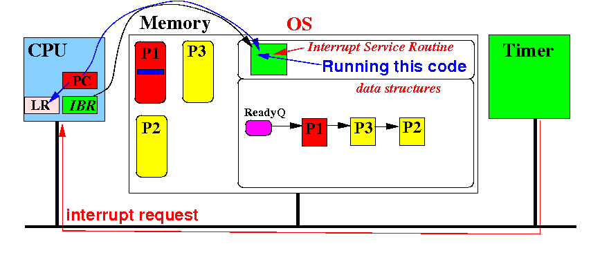
We will now examine the effect achived by the Interrupt Service Routine for the Timer Interrupt.
Step (1) Acknowledge interrupt - the CPU sends out the interrupt acknowledge signal:
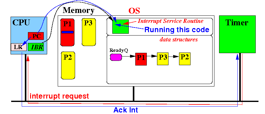
In response: the timer device to withdraw the interrupt signal
Step (2) Save CPU context in the first PCB in the Ready Queue:
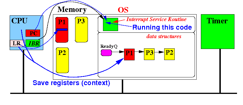
This step enables the Operating System to restart process P1 at a later time
Step (3) Remove the first PCB from the Ready Queue and insert it at the tail:
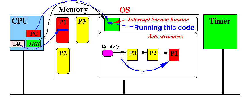
This step will (1) make process P1 the last process and (2) let process P3 run on the CPU.
Step (4) Restore the registers (context) using the values in the first PCB in the Ready Queue:
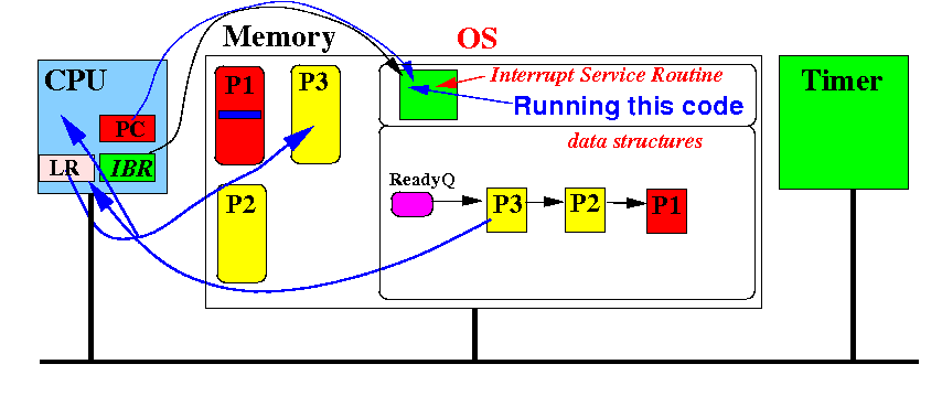
This step will enable process P3 to be resume from the location where it was paused !
Notice that the return address in the LR register points to an instruction in process P3 !
(5) Return (i.e.: mov pc, lr):
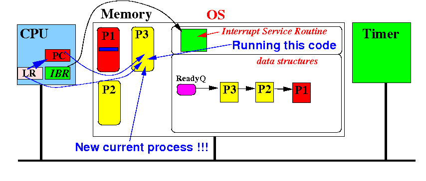
Result: process P3 resumes running on the CPU !
Notice that the process P1 is still in the ready queue and will receive a turn later !!!
