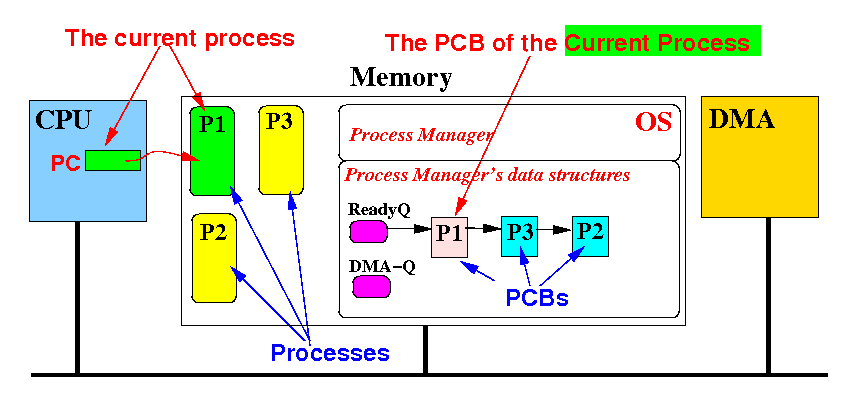
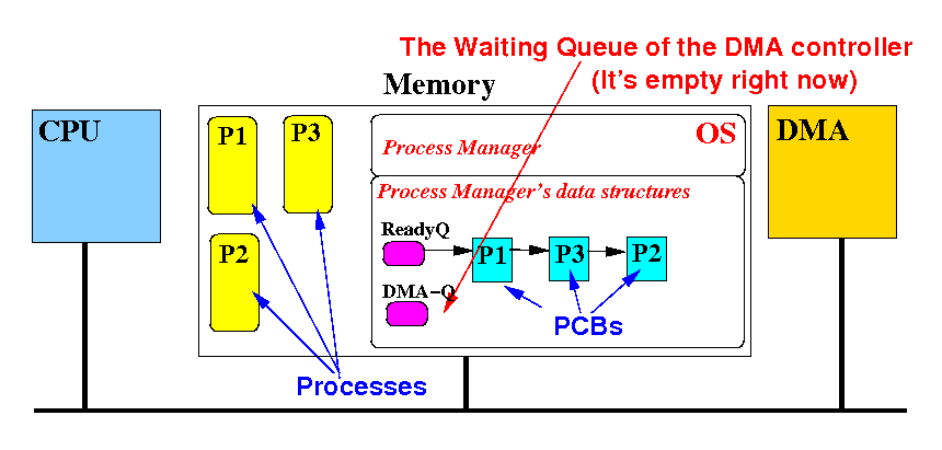
Problem description:
|
|
|
|
|
|
|
|
|
|
|
|
Recall that when a program performs an input operation,
  // Computer program (e.g.: Java)

  i = inputDev.next( ); // Performs an input operation

  i = i + 1; // Must use correct input value !!!
|
the program must wait until the data has been read into the memory before the program can continue execution
|
We will now study how to pause the current process that has performed an input (IO) operation
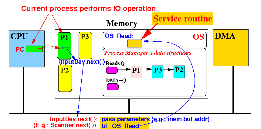
The method call inpuDev.next( ) is translated by the compiler to call a service routine (say: OS_Read) inside the Operating System (with a buffer inside the Scanner object):
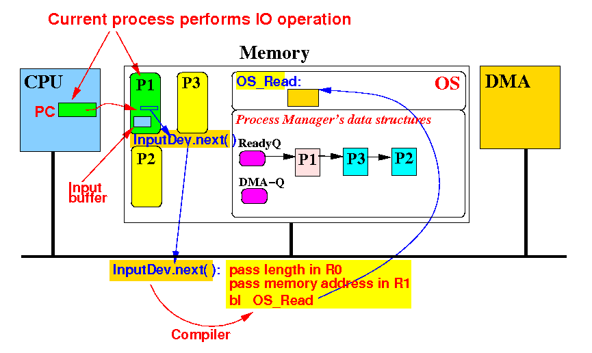
The OS service routine OS_Read() will initialize the DMA to perform the IO operation:
OS_Read: (input params: R0 = length, R1 = buffer address in Scanner object) // Program the DMA to READ 'length' (R0) bytes // into memory location R1 2. Write to DMA length register = R0 Write to DMA address register = R1 Write to DMA command register = READ (1) |
Remember: the current process must be paused !! (Because the input is not ready)
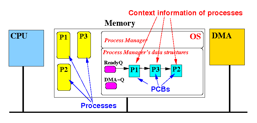
We paused the current process by saving its context information in its PCB:
OS_Read: (input params: R0 = length, R1 = buffer address in Scanner object) 1. Save the context information from the CPU registers into the first element of the ReadyQ 2. Write to DMA length register = R0 Write to DMA address register = R1 Write to DMA command register = READ (1) |
We move the PCB of the blocked process to the DMA-Queue (device queue):
OS_Read: (input params: R0 = length, R1 = buffer address in Scanner object) 1. Save the context information from the CPU registers into the first element of the ReadyQ 2. Write to DMA length register = R0 Write to DMA address register = R1 Write to DMA command register = READ (1) 3. Remove the first PCB (= running process) of the ReadyQ Insert it into the DMA queue |
This represents that fact that the process is waiting for the DMA to finish
The OS_Read( ) routine then load the context information of the first "ready-to-run" process in the Ready queue:
OS_Read: (input params: R0 = length, R1 = buffer address in Scanner object) 1. Save the context information from the CPU registers into the first element of the ReadyQ 2. Write to DMA length register = R0 Write to DMA address register = R1 Write to DMA command register = READ (1) 3. Remove the first PCB (= running process) of the ReadyQ Insert it into the DMA queue 4. Load the context information in the new first element of the Ready Queue into the CPU registers |
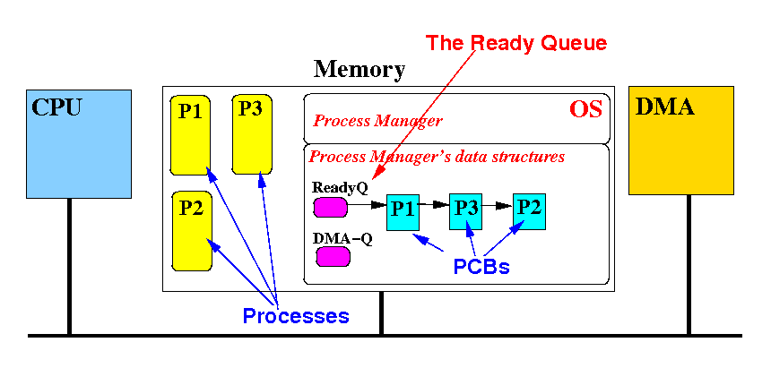
Recall that: the first PCB in the ready queue will always be the (new) current process.
At last, the OS_Read subroutine will return: (where will it jump to ?)
OS_Read: (input params: R0 = length, R1 = buffer address in Scanner object) 1. Save the context information from the CPU registers into the first element of the ReadyQ 2. Write to DMA length register = R0 Write to DMA address register = R1 Write to DMA command register = READ (1) 3. Remove the first PCB (= running process) of the ReadyQ Insert it into the DMA queue 4. Load the context information in the new first element of the Ready Queue into the CPU registers 5. "Return" (mov pc, lr) |
Hint: the link register LR contains the (paused) location of the new ready process !
I will show you the effect of the OS_Read routine using a series of figures

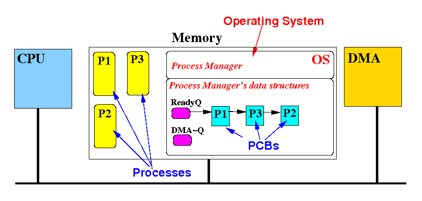
This is the initial state when the current process has just called: inputDev.next( ).
The bl OS_Read instruction will start running the OS_Read routine code:
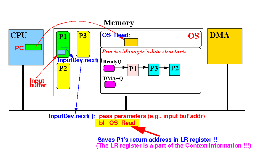
Recall that bl instruction will save the return address into the LR register (=part of the context information)
(1) Save the context information (registers !) from CPU into first element in the Ready Queue
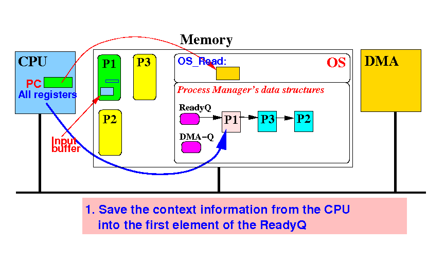
This step enables the Operating System to pause the process P1 and restart P1 at a later time
(2) Start the DMA to transfer data from IO device to P1's buffer:
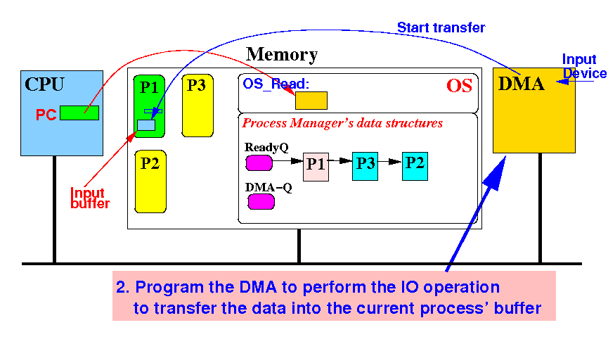
Now the process P1 cannot continue !!! (Because the data transfer is not yet completed)
(3) Remove P1's PCB from the Ready Queue and insert it into the DMA (device) queue:
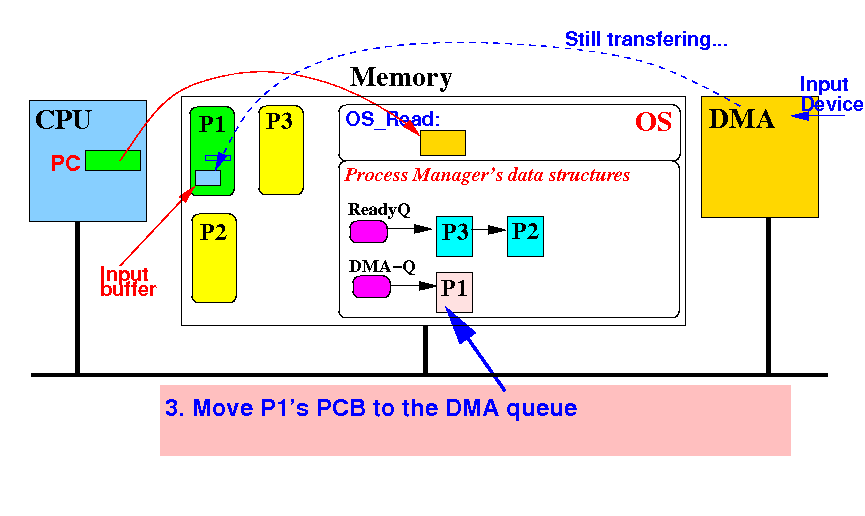
The step enable the Operating System to find P1's PCB when the DMA transfer is done
(4) Use P2's PCB (1st PCB in the Ready Queue) to update the registers in the CPU:
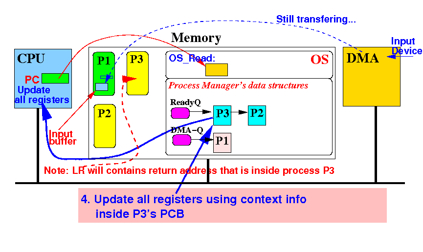
The step enable the Operating System to find P1's PCB when the DMA transfer is done
(5) OS_Read (is a subroutine) returns:
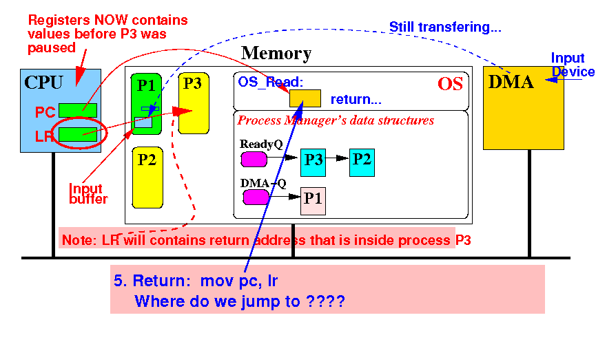
Notice that LR points to an instruction inside the process P3 !!!
Result of the InputDev.next( ) input operation:
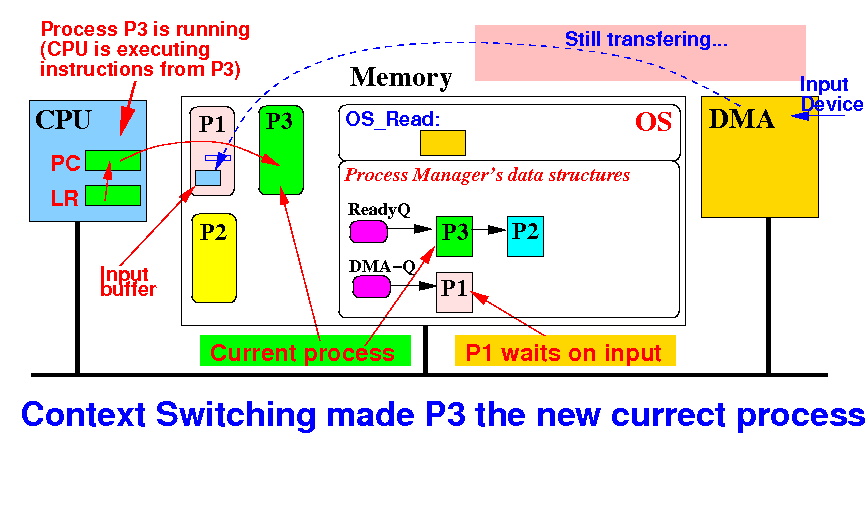
Notice that: (1) P3 is new current process and (2) the IO data transfer is not yet completed
Suppose the input operation completes: P1 can now continue...
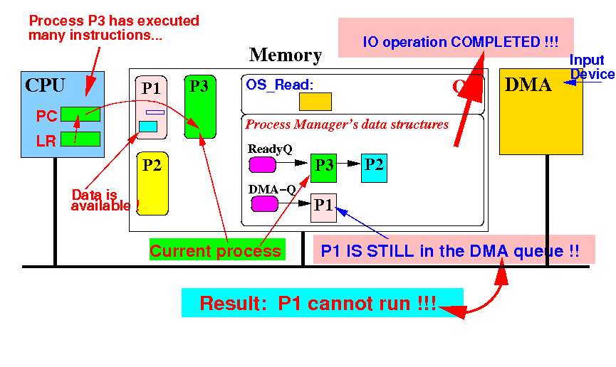
Notice that: P1 is not in the Ready Queue (only processes in the Ready Queue will be executed)
