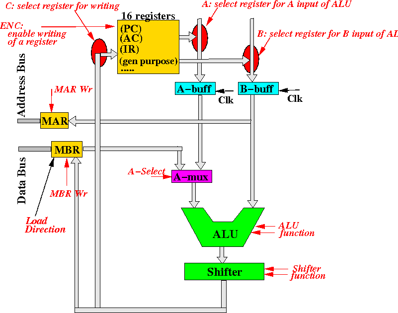
- A: (4 bits) select the register whose output will be used as the A-input
for the ALU [How: use multiplexors]
- B: (4 bits) select the register whose output will be used as the B-input
for the ALU [How: use multiplexors]
- C: (4 bits) select the register for update.
Note: the selected register is only updated if the ENC signal is ONE. - ENC: enable update of some register.
Some instructions do not update registers, like the CMP (compare) instruction (sets flags). The ENC signal will allow the CPU to specify that no registers will be updated. - A-select: controls a set of multiplexors that select the input between
a register or the MBR.
If A-select = 0, the A-MUX multiplexor will select the register as output. And if A-select = 1, the A-MUX multiplexor will select the MBR as output.
By selecting the input from the register, the CPU will perform operations on register data.
By selecting the input from the MBR, the CPU will perform operations on memory data. - ALU function: selects the function that the ALU will perform
(00 = add, 01 = and, 10 = first operand, 11 = not first operand,
as given in Prject 3
- Shifter function: selects the function that the Shifter will perform
(00 = no shift, 01 = shift right, 10 = shift left,
as given in Prject 3
- MAR Write: trigger the MAR (Dffs) to be updated.
Note: by looking at the connections, you must conclude that the MAR will be updated with the value in the B-buffer - MBR Write: trigger the MBR (Dffs) to be updated.
Note: by looking at the connections, you must conclude that the MBR can be updated with data from:
- C-bus (output of the Shifter)
- Databus (data from memory)
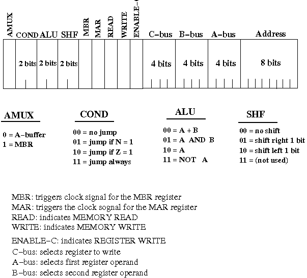
- The various controlling signals are packed together into
a long sequence of bits.
The packing order is chosen by the designer of the CPU and
we choose to pack the bits as follows:

There are 32 bits total in one instruction and these bits control the circuits inside the CPU.
The instruction is stored in the (32 bit) Instruction Register (IR) - it's made with 32 D-flipflops.
This outputs of the IR (which is the instruction code !) is tied to the various part of the CPU which each bit/bits controls. The connections are shown in the following figure:

- Consider the following
machine instruction
inside the Instruction Register:

- The bits in this
machine instructions will
cause the
following data flow paths
to be setup inside the CPU:
- The bits in the A and
B fields
causes the
selection of
registers
R0 and
R6
to be multiplexed to the
A/B-buffers of the
ALU:

The values in registers R0 and R6 will be stored in the A-buffer and B-buffer (these are buffers)
- Then, the
AMUX bit will
cause the
selection of R0 to be
forwarded to the
input of the
ALU:

(The B-buffer output flows to the second input of the ALU)
- Then, the
ALU bits (00)
will cause the
ALU to
compute the
sum of
the ALU inputs:
R0 + R6:

- Then, the
Shifter bits (00)
will cause the
Shifter to
not shift the
input, so the
result will still be
R0 + R6:

The value R0+R6 is now at the input of the registers !!!
- Then, the C field
will select the
register R1;
and the Enable C signal
will enable the
register R1 to
receive
a CLOCK signal:

Register R1 will be updated with the value R0+R6 !!!
- Result of thise execution
is:
R1 = R0 + R6
- The bits in the A and
B fields
causes the
selection of
registers
R0 and
R6
to be multiplexed to the
A/B-buffers of the
ALU:
- Focus on the
memory elements:
- The A/B-buffers and
- The registers
- Visualization:
- We will activate
the different elements
at different times
- We activate
(by channging the clock signal) the
A/B-buffers
first.
(The registers are not activated yet !!!)
The activation will cause the A/B-buffers will "take a snap shot" of the values of the selected registers
(A-buffer snaps the source 1 register and B-buffer snaps the source 2 register)
- After snapping the
values from the
registers,
the A/B-buffers remain
unchange for some time.
During this time, the ALU (and shifter) will compute on the values in the A/B-buffers
- Then we activate
(by changing the clock signal) the
registers.
(The A/B-buffers are not activated !!! So they will retain their values !!!!)
The activation will cause the selected register to "take a snap shot" of the output of the ALU/Shifter
- We will activate
the different elements
at different times
- I have wired the datapath and the controls of the MIR in a demo.
You can invoke the demo by executing:
/home/cs355001/demo/datapath/cs355-demo-dp1- Switch off Reset
first (press key ' (next to the ENTER key)
once)
- Use switches in the top-right hand corner
to setup the
machine instruction that
you want to execute
NOTE: the machine instruction is fetched from memory - we will delay discussion how the CPU read data from memory for later. We will just use switches to similate a fetched instruction.
- After setting up
a machine instruction do:
- Look at the code in the MIR display carefully, see how
it controls the data flow
(The MIR's display is found in the upper-right corner - 2 rows of probes)
The Datapath is completely under the control of the bit setting in a Machine Instruction !!!)
- Toggle keys
h, j, k , l
twice in sequence
- Key j will load data into the A-buffer and B-buffer
- Key l is the clock to write the registers
- Look at the code in the MIR display carefully, see how
it controls the data flow
- Switch off Reset
first (press key ' (next to the ENTER key)
once)
- How to control the CPU to perform
these steps
- (fetch instruction - discussed much later)
- fetch operands (to A-buffer/MBR and/or B-buffer)
- perform the ALU/Shifter operation
- write result to register/MBR
in this exact ordering
|
|