A (live) traffic stop light can be in one of 4 states:
- Red
- Green
- Yellow
- Error (blinking)
A traffic stop light has internal circuitry that do "self-test" and this circuitry would output either Error = 0 (no error detected) or Error = 1 (error detected). When the self-test detects an error, the traffic light would enter the "Error" (blinking) state. Otherwise (no error or a normally functioning traffic light), the traffic light would continuously go through the states Green, Yellow, Red, Green, Yellow, Red, and so on.
The following diagram is a state transition diagram for the traffic stop light:

So the first step in designing a digital circuit that implements a FSA is to represent the states in the FSA's state transition diagram by numbers.
We simply number each state of the diagram. There are 4 states in the traffic stop light FSA and I have assigned the states as follows:
- Red = state 0 (00 binary)
- Green = state 1 (01 binary)
- Yellow = state 2 (10 binary)
- Blinking = state 3 (11 binary)
The state diagram becomes:

- The FSA need to remember its current state
- We have learn about 2 digital circuit that can "remember":
- D-latch
- D-flipflop
- You will see below that the D-latch cannot be used
- Since we have 4 states, we will need two bits to represent the 4 different states.
- Very important: The outputs of the memory devices will represent the state of the FSA
- The way you write/update a D-flipflop (and D-latch) is as follows:
- You first present the value that you want to store in the D-flipflop to the input of the D-flipflop
- Generate a clock/write signal to the D-flipflop's clock input
- The FSA moves from one state to another state
- The state to which the FSA moves depends on
- the error indication signal E
- the current state

- It will have 2 memory elements to remember 4 possible states
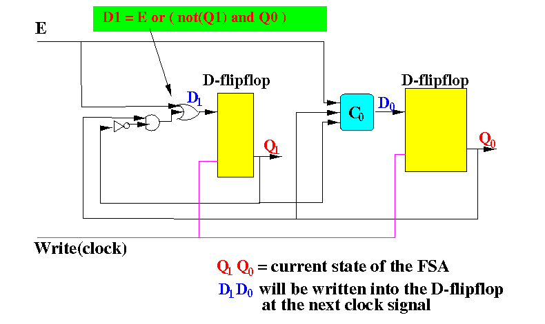
- In the figure, the outputs of the 2 memory elements are Q1 and Q0
- We will need 2 circuits (C1 and C0) to form the value D1 and D0 for the memory elements
- The value D1 and D0 will be written into the memory elements at the next clock signal
- Due to fact that the output of the memory element is used as input to the memory element, the write period must be extremely short, or else the new output value will travel back to the input and form another result which will travel to the output again and form yet another result, and so on and so on.
- The resulting circuit is not stable.


You can construct a (combinatorial) circuit from this table using the circuit design technique described in this webpage and re-enforced in Project 1...
Or, even easier, you may observe that:
- D1 = E or (not-Q1 and Q0)
- D0 = E or (not-Q1 and not-Q0)
And use these two relations to construct circuits C1 and C0 in the above figure.
Here is a partial ciruit diagram (showing only the circuit for D1):

/home/cs355001/bin/cs355sim /home/cs355001/demo/circuits/seq-circuit1-demo |
The following circuit is the same as the previous one, except I have added probes that show the input values to the D-flipflops. This circuit will clearly show how the FSA moves from one state to another:
/home/cs355001/bin/cs355sim /home/cs355001/demo/circuits/seq-circuit1 |
Finally, in the following circuit, I have added a "display" circuit that translates the state into lighting patterns of a traffic stop light:
/home/cs355001/bin/cs355sim /home/cs355001/demo/circuits/seq-circuit1-demo-plus-light |