The effect of a left/right shift operation:

The bits are
shifted one position to
left/right
The open bit position is
filled with a
0 bit
We can redirect the input signals to perform a fixed shift operation:

The bits are
shifted one position to
left/right
The open bit position is
filled with a
0 bit
Shift operation controlled by a control (input) signal:

If the
control signal
Ctrl=0, the
Shifter circuit will
perform a left shift
If the
control signal
Ctrl=1, the
Shifter circuit will
perform a right shift
We can construct the previous (simple) shifter circuit using 2 way multiplexor circuits:

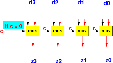
For a 4 bit shifter, we need to use 4 multiplexors (one for each bit):

Connect the (shift) control signal c to the selection input of each multiplexor:

If c=0, the first input (right one) will be selected:

Redirect the input signals to the active mux inputs so the result is left-shifted:

If c=1, the 2nd input (left one) will be selected:

Redirect the input signals to the active mux inputs so the result is right-shifted:

The shifter circuit:

The EDiSim circuit program is shown on next slide - it uses the built-in Mux component
Define Shifter c d3 d2 d1 d0 | z3 z2 z1 z0; /* Bit 3 */ Mux aa c | ZERO d2 | z3; /* Bit 2 */ Mux aa c | d3 d1 | z2; /* Bit 1 */ Mux aa c | d2 d0 | z1; /* Bit 0 */ Mux aa c | d1 ZERO | z0; Endef; |
Notice the
built-in
Mux component
uses 2
| characters
See this webpage for
detail usage information:
click here