Review: A decoder circuit has N control signals and 2N output signals:
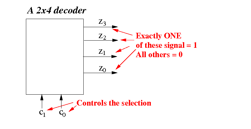
The (one) output which is equal to 1 will be used to activate a circuit (usually a memory circuit)
A demultiplexor circuit has N+1 input signals and 2N output signals:
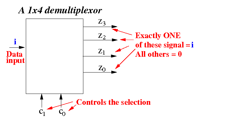
The data input i is switched to exactly one of the outputs - while all other outputs are equal to 0
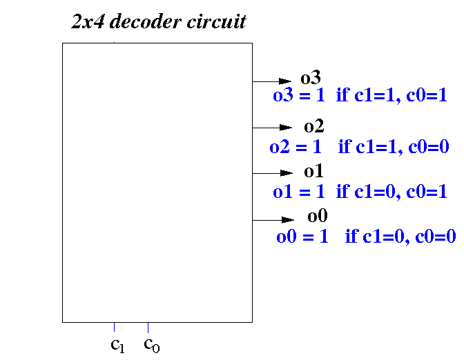
Functionality of the 2x4 decoder:
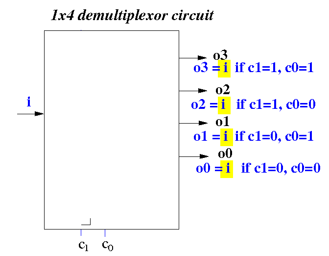
Functionality of the 1x4 demultiplexor:
Internals of a (2x4) decoder:
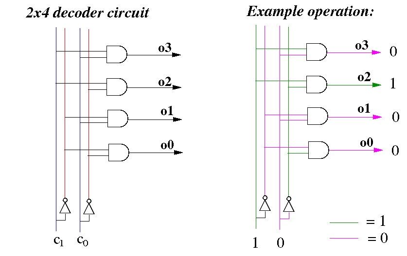
DEMO: /home/cs355001/demo/circuits/decoder
Internals of a (1x4) demultiplexor:
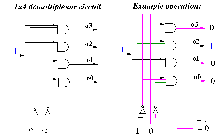
DEMO: /home/cs355001/demo/circuits/demux
|
This simple (one-way) digital switch can switch one signal from any input port onto any output port (= a small (digital) telephone switch):
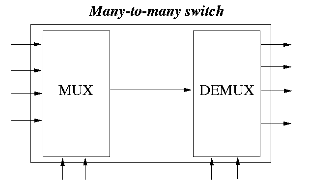
DEMO: /home/cs355001/demo/circuits/mux-demux