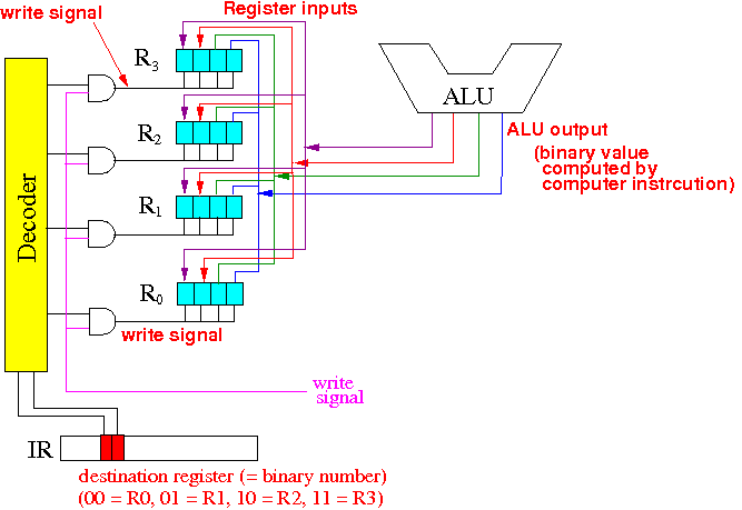
ONLY the register that is being selected will be updated with the output from the ALU. All other registers should keep their old values.
The output of the ALU is ofcourse the result of the computation and we have seen just a while ago how the inputs for the ALU were switched to the ALU using many multiplexors. If you have already forgotten about it, the notes are here: click here
Only the intended register (specified in the computer instruction) will be modified (with the result from the computation which is the output of the ALU). All other registers remain unchanged.

- input: is the bit (0 or 1) that you want to write to the register
- write: is signal that triggers the register to store the current input bit
- output: is the current bit (0 or 1) that is stored in the register
The register is similar to a single-memory calculator (you know, the kind you buy for $2.99..., it has a Min (store), MC (clear), M+ (add) and M- (subtract) keys...). When you press Min (Memory Input), the value on the display is stored. As long as you do not press Min, the value in the memory remains unchanged.
The input signal is the display of the calculator, the write signal is the Min key and the output signal is the value inside the memory.
When we wire the register for writing (updating), we don't need to wire the output signal of the register, so I will show only the wiring of the input and the write signals. (FYI, the output of the register is wired to the input of the MUX's so that the ALU can obtain the values stored in the register - see here: click here)
To form a multi-bit register, you use multiple one-bit registers. In the example below, I used 4-bit registers, so there will be 4 "one-bit registers" that make up one "4-bit register".

- The output of the ALU is connection to the input of every register.
- But remember that a register is only updated when it receives a write signal (i.e., pressing Min)
- The CPU will generate a write-signal to write a specific register - this signal is given by the magenta-colored line.
- The decoder and the 4 AND-gates are used to filter the write-signal so that only the register specified by the destination operand inside the computer instruction will be selected for update.
- Thus: only the register indicated by the computer instruction will be updated with the output of the ALU (which is the result of the computation indicated by the current instruction.
- (I won't explain how registers work yet - will be covered later).
- This is the demo on how to use a decoder
to select one of the register for writing:
click here
/home/cs355001/bin/cs355sim /home/cs355001/demo/circuits/alu-regHow to operate this circuit:
- Use keys 0, 1, 2, 3
to set a value which represents the outputs of the ALU
- Use keys a, b
to control the decoder
used to select one of the registers to write the value to.
You can see in the probes next to the decoder which register is selected.
- Finally, use the key c
to trigger (= send) the WRITE signal.
You must tap key c twice to complete the write, because that's how the clock signal in the CPU works to write registers: by turning it on and then off.
- Use keys 0, 1, 2, 3
to set a value which represents the outputs of the ALU